I’m performing Side Channel Analysis on a third party target board, a PIC18F27K42 MCU. I’m using SimpleSerialV1 and TinyAES128, in a very similar way to what happens for native ChipWhisperer targets.
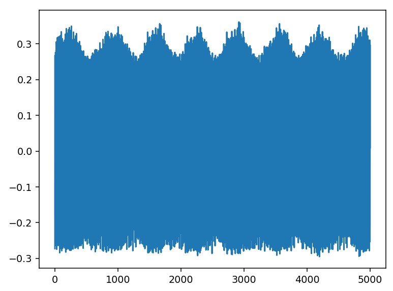
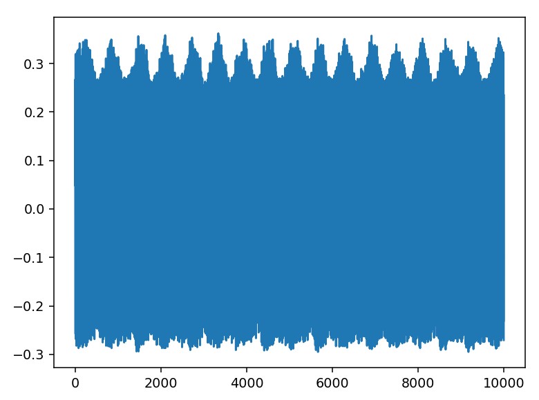
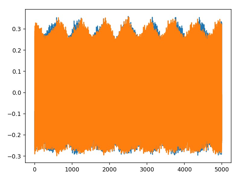
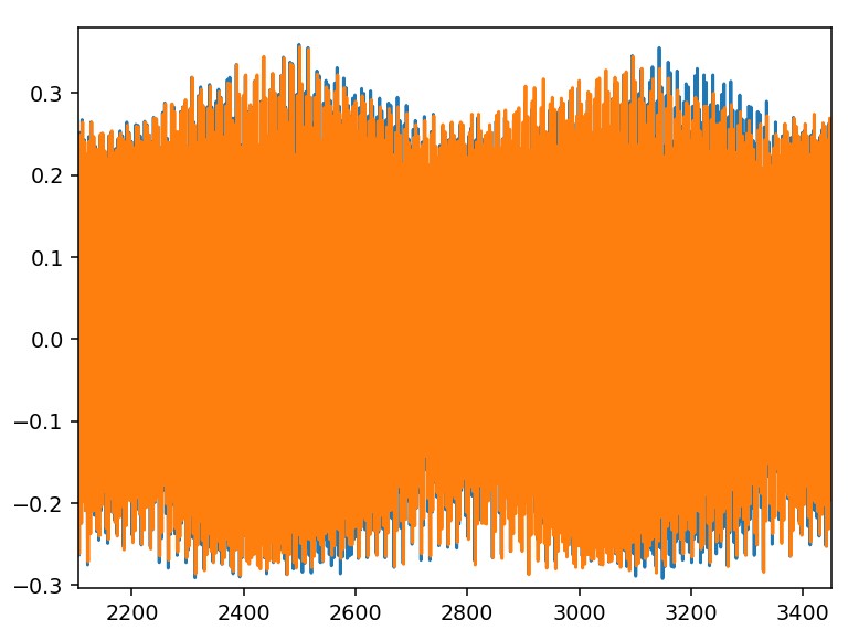
I wanted to perform a SPA at first, to see all rounds of interest in AES but the waves are not promising at all…
I wanted to ask you the heuristics for performing an attack. So far I:
measured power across the shunt resistor (around 50 ohm) and also tried across the MCU (I think across the resistor it should be better since the MCU should be a kind of variable equivalent resistor, am I wrong?);
changed resistor to higher and lower;
tried to measure with shunt resistor upstream and downstream the MCU;
powered the MCU to 3.3 and 5V (it supports both);
shortened as much as possible the clock and measure cables.
If anyone has advice about anything I might try doing, please tell me. I’m getting kinda desperate!
I do not have a semicoaxial cable to perform measure, do you think it might be the source of much noise? I’m using normal jumper cables, around 8cm long.
To me this looks like noise, but I don’t understand why. Maybe the MCU doesn’t leak sufficiently? The encryption is done properly and the setup is mounted correctly, according to what I read also in the " The Hardware Hacking Handbook: Breaking Embedded Security with Hardware Attacks" book.
Update, for anyone that is interested into the topic:
I wondered what is the optimal experimental setup, thus I used the program “basic_passwd_check.c” to lead some experiments. It turns out that I have a better SNR when:
I connect the shunt resistor between power supply and Vcc;
I do not connect both GND pins (the PIC18 MCU I am using has two) to 0V.
I will use this setup for my experiments on AES-128.
P.S. This does not solve my problems for the SPA on AES-128, so if anyone can help me I would be grateful!
Hi, thank you for the reply. The PIC MCU I am using seems to have an internal voltage regulator that is only used to make the wake-up time shorter, by keeping the voltage higher. Do you think this is the problem? I never set it in sleep mode.
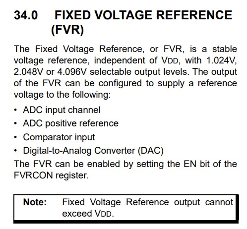
On the other hand, the datasheet shows a Fixed Voltage Regulator, described as follows:
Do you think this might cause much noise?
The potential issue with voltage regulators is that it tries to maintain the target voltage constant, so it will hide or distort the small power fluctuations that we want to measure for successful side-channel power analysis. Same with decoupling capacitors. The link I shared has some notes on overcoming voltage regulators. Decoupling capacitors need to be removed.
Jean-Pierre
unfortunately the datasheet doesn’t even say which pin the voltage regulator is attached to, it is unaccessible. Do I have to assume that it is placed at the Vdd pin? It is the only Vdd pin available for the MCU.
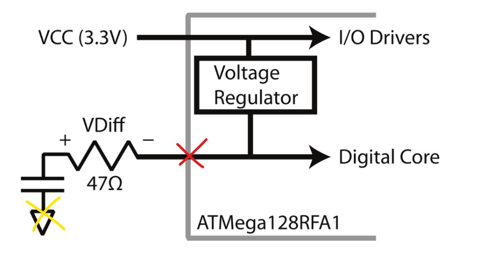
I want to replicate this setup:
Assuming that the red ‘X’ is the Vdd pin I was referring to, does the yellow ‘X’ correspond to the Vss pin of the MCU? Or do I have to just connect the RC to any ground reference?
I’m asking this because in the suggested setup on the datasheet they put a decoupling capacitor between Vdd and Vss (that I never put). In the drawing I attached here it seems I have to put such a decoupling capacitor, with the resistor as well.
As to the location of the probes, do I have to measure across the shunt? It seems so. If so, I connect the ‘-’ side to the “MEASURE” port and the ‘+’ side of the resistor in the picture to the GND of the “MEASURE” port, or am I wrong?
In that case you might be out of luck with this approach.
Yellow X is ground (Vss). The red X is the output of the internal voltage regulator, which it looks like you don’t have access to in your target. You can look at the ATMega128RFA datasheet (which our diagram is based on) for more context on that.
I solved the issue. I moved the trigger way closer to the SubBytes and performed “reverse CPA” as a check to see if there was a correlation between plaintext and traces deriving from such plaintext. Seems to work.
Thank you both for the help!
Awesome, I’m happy to hear that! Sometimes traces may not look like much yet still contain the leakage required for a successful attack. Thank you for the update.
Jean-Pierre
 (unless the AES is far away from the interval you’re looking at, but I assume it’s not the case)