Faultapp1 python errors

So I rebooted my computer and the [Failed] change back to [NORMAL]. I happened to see a small dip in the reading across the resistor, then it started to fail again. I have to reboot my computer again so I can do more testing.

I also happened to notice a solid red led next to the USB port. I’m not sure what that means, but I think it is relevant.

Now that I said that, it isn’t working at all.

I rebooted the VM twice , unplugged and plugged in after logging into the VM and I cannot connect to the CWLITE.

third time was the charm, but I still ONLY get [FAILED].

Since this is associated with the nxpprog connection I can only assume it has to do with the serial connection.

this time I don’t have the red LED.

Ah sorry, I didn’t realize that the Nano was shown there. The Nano can technically perform the lab, but I highly recommend the Lite because the python API for the Nano is pretty different, meaning you’ll have to make some changes to the setup to get this to work. The glitch is also pretty precise and the Lite can insert much more accurate glitches, in both time and width, so it should make the glitch much more reliable once you get it.

The red LED just lets you know that the ADC on the CW-Lite is unlocked. We’re not using the ADC, so that’s fine here.

The fact that this is working so intermittently kind of makes me think this is a bad connection somewhere, but I could be wrong. Do you mind taking some pictures of your setup so I can see if anything is out of the ordinary?

Also, do you think you can run 'print(scope) just before the block where you try glitching, so I can see if anything is weird in the scope setup?

One thing you can try to debug the glitch itself is to run scope.glitch.manual_trigger() once everything is setup, which should insert a glitch without having to trigger it via the nRST pin.

Alex

cwlite Device
sn         = 50203220313038543130333236323038
fw_version = 
    major = 0
    minor = 60
    debug = 0
gain = 
    mode = low
    gain = 0
    db   = 5.5
adc = 
    state          = True
    basic_mode     = rising_edge
    timeout        = 2
    offset         = 0
    presamples     = 0
    samples        = 10000
    decimate       = 1
    trig_count     = 1300240852
    fifo_fill_mode = normal
clock = 
    adc_src       = clkgen_x1
    adc_phase     = 0
    adc_freq      = 199999992
    adc_rate      = 199999992.0
    adc_locked    = False
    freq_ctr      = 0
    freq_ctr_src  = extclk
    clkgen_src    = system
    extclk_freq   = 10000000
    clkgen_mul    = 25
    clkgen_div    = 12
    clkgen_freq   = 200000000.0
    clkgen_locked = True
trigger = 
    triggers = tio4
    module   = basic
io = 
    tio1         = serial_rx
    tio2         = serial_tx
    tio3         = high_z
    tio4         = high_z
    pdid         = high_z
    pdic         = high_z
    nrst         = high_z
    glitch_hp    = False
    glitch_lp    = True
    extclk_src   = hs1
    hs2          = None
    target_pwr   = True
    tio_states   = (0, 1, 0, 1)
    cdc_settings = bytearray(b'\x01\x00\x00\x00')
glitch = 
    clk_src     = clkgen
    width       = 39.84375
    width_fine  = 0
    offset      = 10.15625
    offset_fine = 0
    trigger_src = ext_single
    arm_timing  = after_scope
    ext_offset  = 0
    repeat      = 1
    output      = enable_only

This is the connection to the probes. I did check that the resisitor is not bridged. It reads 10 Ohms if I measure pad to pad.

This is the probe connection

This is the reset connection and UEXT connections.

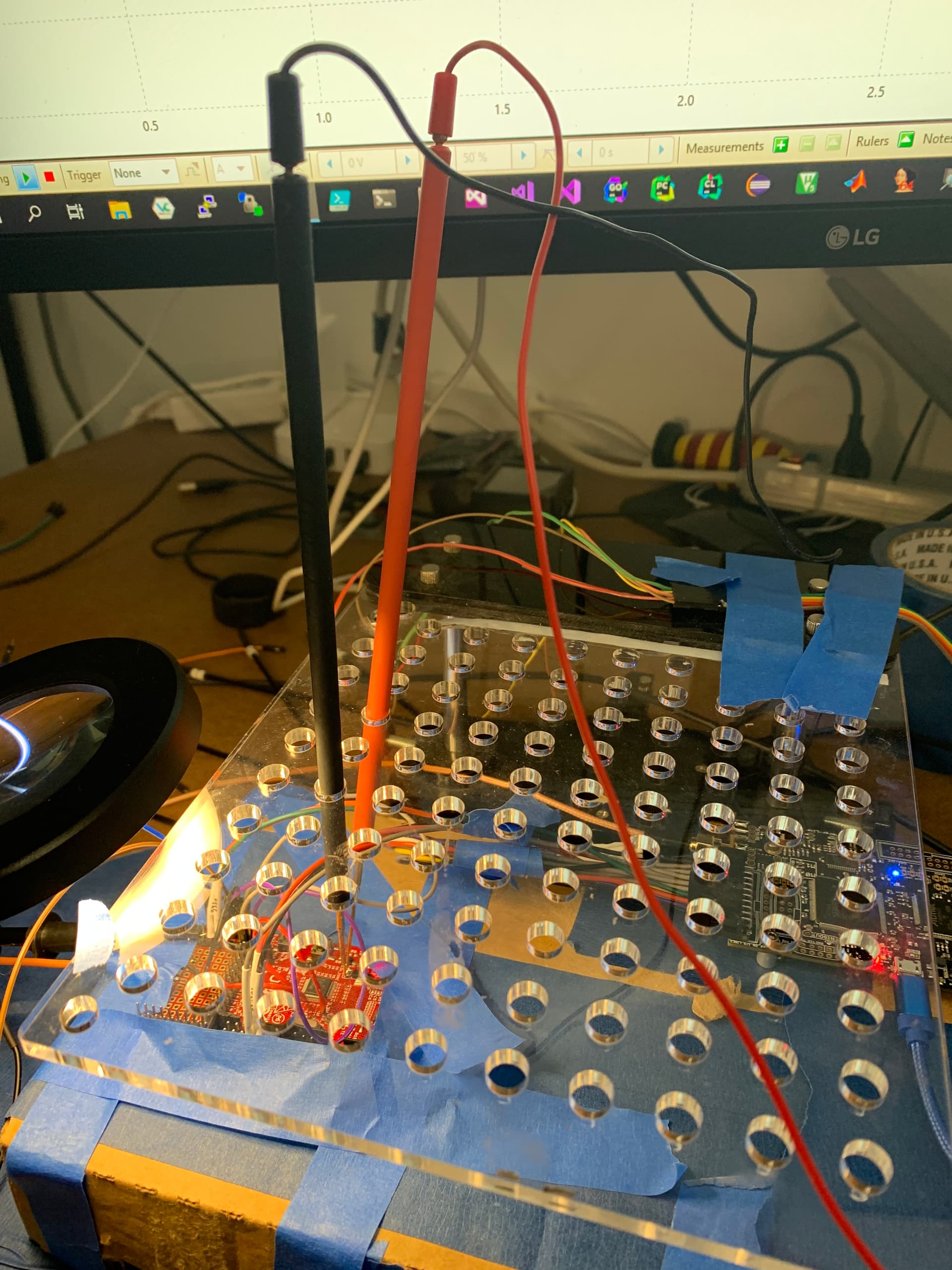
Since you thought it might be a loose connection I changed the probes. The probes I used have 0.3mm pin spring. These new ones are a little heavier duty and the probes they have a little more weight too.

This time it cycled through all of the time and glitch width options. It returned [NORMAL] every time. I had also mad the modifications to the /etc/udev/rules.d/50-newae.rules (mention in thread: Unable to communicate with found ChipWhisperer - #9 by Alex_Dewar - ChipWhisperer Software - NewAE Forum)

So what is left, is why am I not getting a glitch?

Your settings look okay. Try running the following in the block above where you try glitching:

scope.glitch.repeat = 20*freq_multiplier
scope.glitch.offset = 0
scope.glitch.manual_trigger()

If you change your oscilloscope to trigger on the power trace instead of on the reset pin, do you see a glitch? What about if you try running through with a freq_multiplier of 0.5?

Alex

I ran the block of code under a multiple of 2 and 0.5, never saw a glitch.

looking through the code, I don’t see where the glitch is being fired.

import time
from binascii import unhexlify

print("Attempting to glitch LPC Target")

scope.io.target_pwr = False
time.sleep(0.2)
scope.io.target_pwr = True
time.sleep(0.2)


nxpdev = CWDevice(scope, target)

done = False
while done == False:
    scope.glitch.ext_offset = offset_range.min
    if scope.glitch.repeat >= repeat_range.max:
        scope.glitch.repeat = repeat_range.min
    while scope.glitch.ext_offset < offset_range.max:

        scope.io.nrst = 'low'
        time.sleep(0.05)
        scope.arm()
        scope.io.nrst = 'high'
        target.ser.flush()
        
        print("Glitch offset %4d, width %d........"%(scope.glitch.ext_offset, scope.glitch.repeat), end="")

        #scope.capture()
        #plot.send(scope.get_last_trace())
        
        time.sleep(0.05)
        try:
            nxpp = nxpprog.NXP_Programmer("lpc1114", nxpdev, 12000)

            try:
                data = nxpp.read_block(0, 4)
                print("[SUCCESS]\n")
                print("  Glitch OK! Beginning dump...")
                
                datafile = None
                
                for i in range(0, 0x7FFF, 16):
                    data = nxpp.read_block(i, 16)
                    st = " ".join(["%02X"%ord(b) for b in data])
                    print(st)
                    
                    if datafile is None:
                        datafile = data
                    else:
                        datafile += data
                    
                
                with open("lpc1114_dump.bin", "wb") as f:
                    f.write(unhexlify(datafile))
                with open("lpc1114_dump_ascii.bin", "wb") as f:
                    f.write(datafile.encode('latin-1'))    
                
                
                done = True
                break

            except IOError:
                print("[NORMAL]")
    
        except IOError:
            print("[FAILED]")
            pass
    
        scope.glitch.ext_offset += offset_range.step

    scope.glitch.repeat += repeat_range.step

Also I set a trigger. Once the reset happens the gitch goes low momentarily as well which triggers the trigger.

I moved the B (Red) lower on the screen, to make sure I was not missing the glitch behind the Red.

It started to fail again. It had been working all morning.

  • I unplugged the CWLite from the USB
  • I rebooted the VM
  • I logged in
  • I plugged the CWLite into the USB
  • I ran the Jupyter Cells

All I am seeing is [FAILED]

Attempting to glitch LPC Target
Glitch offset 2590, width 10…[FAILED]
Glitch offset 2591, width 10…[FAILED]
Glitch offset 2592, width 10…[FAILED]

I even rebooted my computer. I fully understand why that should not matter. It did seem to help yesterday, so I tried it again today.

I checked and double checked al my connections.

  • The Serial TX & RX are solid
  • glitch cable is tight on both ends
  • probes are all on point and reading good.

Some additional troubleshooting that I did.

After running the setup portions of the lab I ran this

nxpdev = CWDevice(scope, target, print_debug=True)

#Need to enter ISP mode before initializing programmer object
nxpdev.isp_mode()
nxpp = nxpprog.NXP_Programmer("lpc1114", nxpdev, 12000)

#Examples of stuff you can do:
print("Reading Serial number...")
print(nxpp.get_serial_number())
print("Reading bytes")
print(nxpp.read_block(0, 4))

and this is what I saw

Write: ?
Read: 
---------------------------------------------------------------------------
OSError                                   Traceback (most recent call last)
<ipython-input-5-8645dc98de0d> in <module>
      3 #Need to enter ISP mode before initializing programmer object
      4 nxpdev.isp_mode()
----> 5 nxpp = nxpprog.NXP_Programmer("lpc1114", nxpdev, 12000)
      6 
      7 #Examples of stuff you can do:

~/work/projects/chipwhisperer/jupyter/courses/faultapp1/external/nxpprog.py in __init__(self, cpu, device, osc_freq, verify)
    520         self.cpu = cpu
    521 
--> 522         self.connection_init(osc_freq)
    523 
    524         self.banks = self.get_cpu_parm("flash_bank_addr", 0)

~/work/projects/chipwhisperer/jupyter/courses/faultapp1/external/nxpprog.py in connection_init(self, osc_freq)
    530 
    531     def connection_init(self, osc_freq):
--> 532         self.sync(osc_freq)
    533 
    534         if self.cpu == "autodetect":

~/work/projects/chipwhisperer/jupyter/courses/faultapp1/external/nxpprog.py in sync(self, osc)
    627         s = self.dev_readline()
    628         if not s:
--> 629             panic("Sync timeout")
    630         if s != self.sync_str:
    631             panic("No sync string")

~/work/projects/chipwhisperer/jupyter/courses/faultapp1/external/nxpprog.py in panic(str)
    394 
    395 def panic(str):
--> 396     raise IOError(str)
    397 
    398 

OSError: Sync timeout

Ok so I fixed that issue. I closely examined the board and I had a piece of loose solder bridging the center post and the shield on the SMA connector that I attached to the LPC1114 dev board. I had taken a measurement across those pins earlier today.

@Alex_Dewar sorry about the few posts above. I still have one issue. I’m not seeing the glitch.

It’s back. I think I’m going to start over and re mod a different board.

Try uncommenting scope.capture(). I think if you don’t run that, the scope won’t rearm properly and therefore the glitch won’t fire after the first time

Alex

@Alex_Dewar

I built a new board. I paid close attention to the areas I had issues with. I put some heat shrink around the sma V+ post connection, so there would be no bridging there, and I made much better solder joints for the cable that got soldered on the pads going to the sma. The solder connections for the 10 ohm resistor are also a bit cleaner.

The black wire connects to the sma connector on the back of the board, to the shield.

The ground pins are on the left, and I moved the reset to the right.

I just ran through the entire cycle with the multiplier = 2. Still no glitch occurring.

I monitored the reset in Red and the voltage across the 10 ohm res in blue. I set the blue channel to AC coupled in the OScope. I thought it would be more obvious that way.out

image

I would have thought I would see the blue dip to the on the bottom very noticably.

I also added a T connector to the sma and connected both glitch and measure to the T along with uncommenting the

scope.capture()

as you mentioned.

I also ran it using a multiplier of 0.5 and 1. Neither produced anything.

I’m not too sure why it isn’t working then. Do you have a CW308 based target to try voltage glitching on, just to rule out a hardware problem? You could try running through one of the fault101 voltage glitching labs.

Alex

Update: I found that by taking a measurement on either side of the resistor, often interfered with the nxpprog from communicating with the device. I tried to run the block ofcode thathas

print(nxpp.get_serial_number())
print(nxpp.read_block(0, 4))

It would fail if I messured. If however I removed the probes it would work. Then I moved the ground of the probe to the GND pins on the board and placed the red probe on the one side of the resistor I was able to get the reading I as looking for and nxpprog worked.

With this I was able to also run the DPA steps, which I missed before because they never worked with my setup.

With this configuration I was able to perform the attack using the code provided.

Good to hear you got that figured out! Not sure what your measurement system looks like, but if that negative lead went to the ground lead of a scope, I can see how that might cause issues - they’re typically hooked up to earth ground, not isolated like on a multimeter.

Alex