@Alex_Dewar Thank you very much!
HI! @Alex_Dewar
I met the another question.
Actually, I try to implement the VCC-glitch attack on the CW305.(My purpose is attacking the TRNG which was programmed in the FPGA)
@Alex_Dewar
I think it still need to program the fw_path,right?
If not ,the following tutorial cannot move.Because I use 2-part version,I cannot set the “PLATFORM=CWLITEARM”
please help me
This error is caused by the target’s trigger not going high. Similar to an oscilloscope, we need a trigger for the glitch to activate after arming the ChipWhisperer. How is your target setup to communicate? SimpleSerial is all UART based, so it may or may not be what you’re looking for here.
Jupyter’s setup like an interactive Python. It’s fine to edit blocks to remove things you don’t want to run or to skip them entirely.
A few links that might be useful for you, if you haven’t seen them yet:
- The documentation page for the CW305: CW305 Artix FPGA Target - NewAE Hardware Product Documentation
- Notebook for attacking AES on the CW305: chipwhisperer-jupyter/demos/PA_HW_CW305_1-Attacking_AES_on_an_FPGA.ipynb at master · newaetech/chipwhisperer-jupyter · GitHub. It shows you all the basics for setting up the CW305, usual communication, etc.
- We recently released a “how to” for running side channel attacks on the CW305: http://media.newae.com/appnotes/NAE0010_Whitepaper_CW305_AES_SCA_Attack.pdf. It’s somewhat focused on CPA attacks on AES; however, I believe sections 2 (glitching is actually pretty similar in how it’s setup, it just the trigger causes a mosfet to pull the target Vcc low instead of triggering the ADC), 3, and 8 would be useful as well.
Alex
HI! @Alex_Dewar
I try to connect the target to the capture in order that section 3 mention.
But still Stuck in this tutorial.
If I just try to see the glitch effect on my target not trying to break the cryptographic algorithm, which steps do I need to do ?
I am rookie jupyter python user.
Thank a lot to your help!
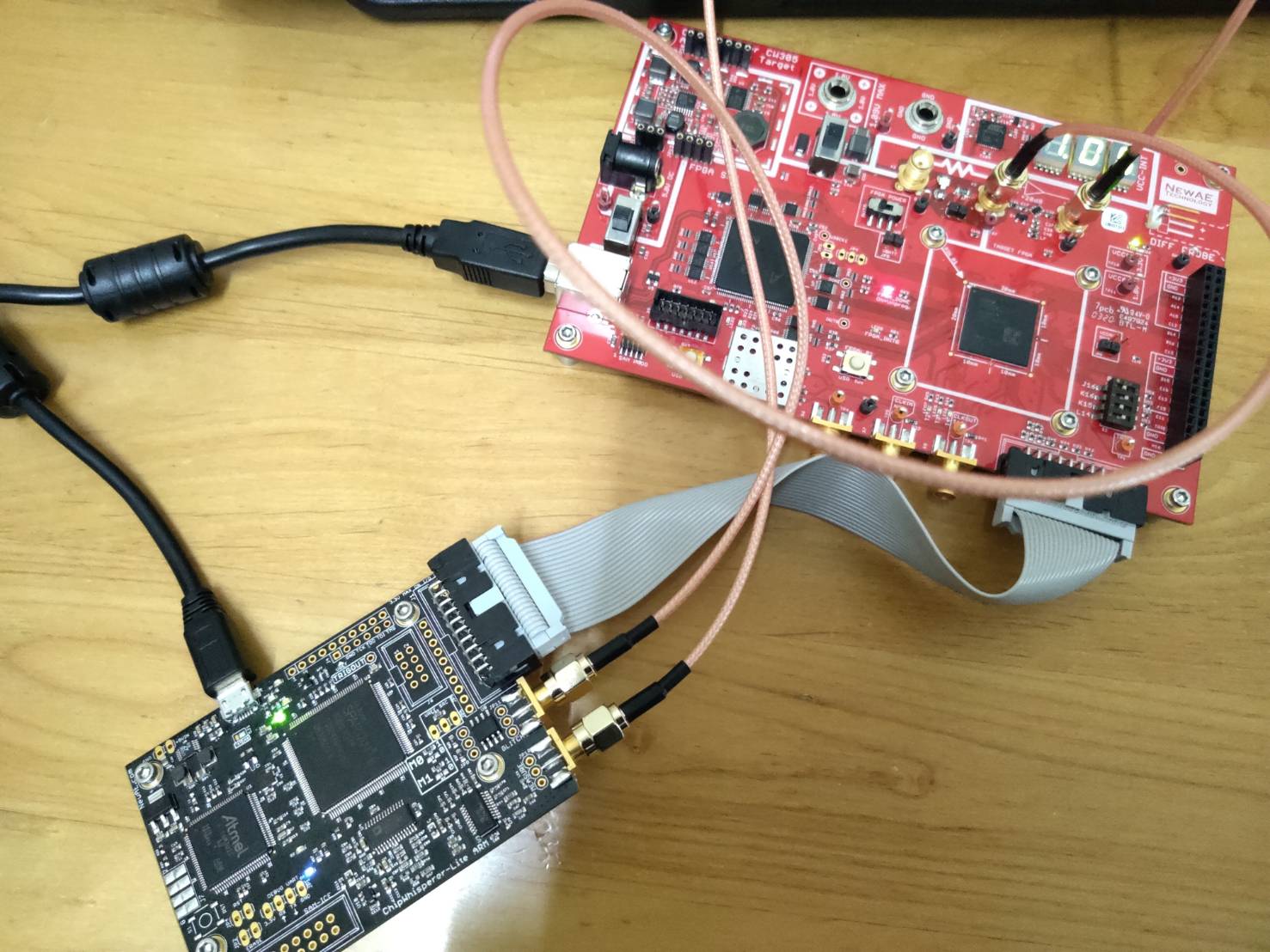
This is my hardware connecting.(measure to X4) (glitch to X3)
Basically, on the target side, you need to:
- Have a way for the Python to trigger the CW305 to do the operation you want (in this case the TRNG). For example, for AES running on a microcontroller, the sending of the plaintext triggers the microcontroller to do an AES encryption on that plaintext.
- As the operation you’re interested in is starting, the CW305 will need to set a trigger pin high to trigger the glitch module on the ChipWhisperer
- Have some sort of feedback to be able to determine glitch success
On the software side you need to do the following:
- Connect to the ChipWhisperer (
scope = cw.scope()). For a default CW305 configuration, typically callingscope.default_setup()(see readthedocs for what this does) should be sufficient. - Connect to the target. The CW305’s bitstream is stored in volatile memory, so you’ll probably have to program the CW305 on startup:
target = cw.target(scope, cw.targets.CW305, bfile='/path/to/bitstream', force=True) - Do some setup on the CW305. Typically the following is sufficient, assuming you only need one clock on FPGA pin N13:
target.vccint_set(1.0) #set target voltage to 1.0V
# Setup only PLL1 to output
target.pll.pll_enable_set(True)
target.pll.pll_outenable_set(False, 0)
target.pll.pll_outenable_set(True, 1)
target.pll.pll_outenable_set(False, 2)

# run PLL1 at 10 MHz:
target.pll.pll_outfreq_set(10E6, 1)

# 1ms is plenty of idling time
target.clkusbautooff = True
target.clksleeptime = 1
- Setup the glitch module:
scope.glitch.clk_src = "target" # set glitch input clock
scope.glitch.output = "glitch_only" # glitch_out = glitch
scope.glitch.trigger_src = "ext_single" # glitch only after scope.arm() called
scope.io.glitch_lp = True
Once you’ve got all the setup done, you need to make a glitch loop. This will look something like:
import chipwhisperer.common.results.glitch as glitch
gc = glitch.GlitchController(groups=["success", "reset", "normal"], parameters=["width", "offset", "ext_offset"])
gc.display_stats()

gc.set_global_step(g_step)
gc.set_range("width", 5, 48)
gc.set_range("offset", -49.8, 49.8)
gc.set_range("ext_offset", 5, 20)

for glitch_setting in gc.glitch_values():
    scope.glitch.offset = glitch_setting[1]
    scope.glitch.width = glitch_setting[0]
    scope.glitch.ext_offset = glitch_setting[2]

    scope.arm() #arm the glitch module

    #---do whatever you need to to get the target to start the desired operation

    ret = scope.capture()

    # determine glitch success
hi @Alex_Dewar
I want to ask how to make my target to trigger the CW-LITE glitch module?
Is mean use one of tio1~4?? If is ,How to do it in practice?
Because I don’t find any trigger the glitch module in the tutorial, I am very appreciate your help!
I believe any of TIO1-4, as well as nRST can be used as a trigger pin, but TIO4 is the default (for the target triggering the ChipWhisperer). Also, the trigger for the glitch module is always rising edge. In lab 1_1/lab 2_1, the glitch firmware on the target is triggered to run by sending it "g\n" over UART. Once the microcontroller receives that, it sets pin TIO4 high, does its loop calculation (which in your case would be the TRNG), then sets the trigger pin low.
Relevant docs: https://chipwhisperer.readthedocs.io/en/latest/api.html#chipwhisperer.scopes.OpenADC.trigger
Alex
I try to setup my .xdc file and verilog design to make the trigger pin(tio4) be high when I need it.
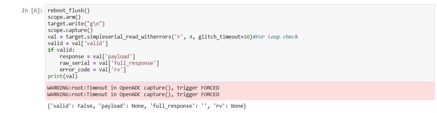
But my glitch control still was “WARNING:root:Timeout in OpenADC capture(), trigger FORCED”
I think it means my target(CW305) didn’t send the trigger to CW-lite through the 20-pin,right?
Is it necessary to use the method you mention below? Because I only have the TRNG module in my design,don’t have usb_module,registers.v…
Yup, that’s correct.
You just need a way to:
- Start a TRNG operation
- Set a trigger pin high
- Some way to observe the effects of glitches
Using the normal USB interface is a way to accomplish these things, but any way you can accomplish these things will be fine.
Alex
HI, @Alex_Dewar Thanks for your help!
I find some problems in my experiment. I observe the glitch modules working from the jupyter notebook.
But my design doesn’t perform any response, I want to use oscilloscope to observe if the glitch really happen.
Where can I connect my probe to the CW305? I try to use SMA to connect to oscilloscope, but the size is different from the oscilloscope and the X4 on the CW305.
Are you just looking to see the glitch waveform? Oscilloscopes usually have a BNC connector, not an SMA like the ChipWhisperer. You’ll need an adapter to connect the two.
Alex
Yes, I just want to check the wave of the vcc glitch.
Did it have another method to get the goal?
If it’s, please teach me how to do.
Thank for your help again.
If you have a differential probe, you can use JP7 (located next to the shunt resistor). A regular oscilloscope probe will work on TP7 below X3.
Alex
HI @Alex_Dewar
When I do some experiments, I met some problems:
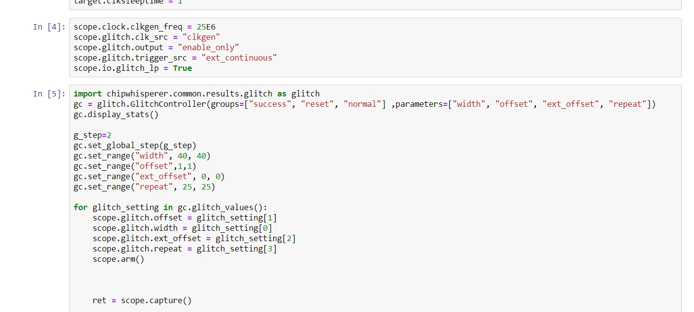
1,I set the trigger as the 250KHz ,and the parameters are “ext_single”,“clkgen(25E6 HZ)”,“enable_only”,“repeat=25”. The ideal result I want to see is 1us glitch per 4us ,but actually what I observe on the oscilloscope is nothing.(I use scope.default_setup() for my setting)
2, When I change the “ext_single” to “ext_continuous”, I see some glitch sequences which were trigged per 0.01s (not meet my trigger’s frequency)
3, when I do the experiments with small width glitch and high frequency triggers(about 25MHz) with “ext_single” , I also cannot observe anything on the oscilloscope.
Please tell me what happen, thank a lot.
For ext_single, the glitch will only fire after scope.arm() is called. I’m guessing based on your parameters there that your loop with scope.arm() never runs, so this is probably expected. ext_continuous will fire the glitch without needing scope.arm() to be called.
You’re probably running into the same issue as above. That being said, this is definitely too high of a frequency to be glitching at. enable_only pulls the voltage low for a full clock cycle and repeat repeats the glitch, so glitching above 1MHz doesn’t make any sense.
This one I’m not too sure on. Maybe try reducing repeat or increasing clkgen_freq?
Alex
@Alex_Dewar So all I want to do is setting the glitch parameters(width,offset,ext_offset), and trig it at specific frequency , and wanting the LITE to deliver the vcc glitch at that frequency.
please tell me how to edit my python code,and my trigger 's behavior is like the clock.(01 change at the
fixed frequency)
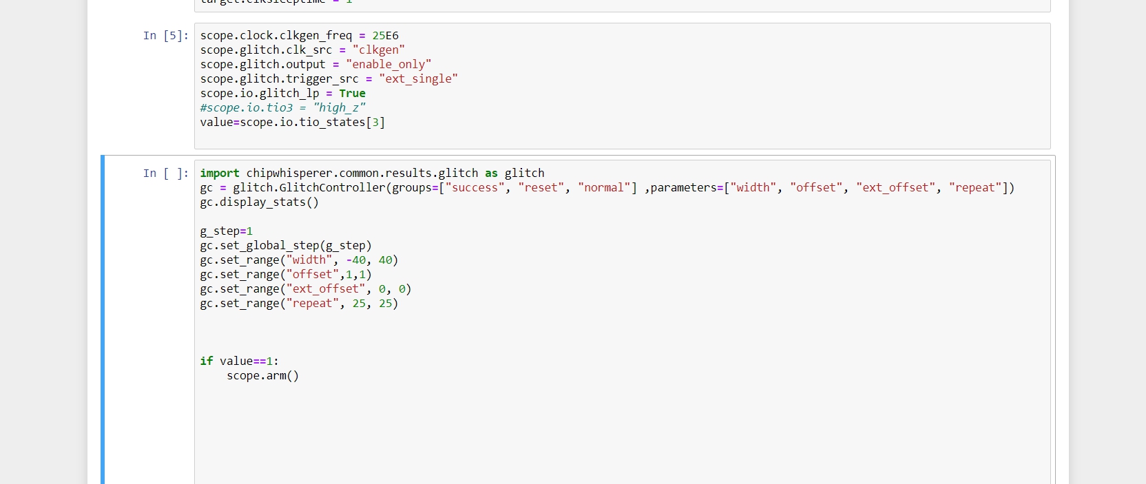
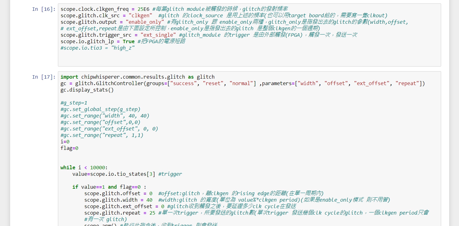
The new version of my python code,but the problems in last time weren’t solved.
thanks a lot
It sounds like ext_continuous would work better for you as that would allow you to avoid having to arm the scope to glitch.
I can’t replicate your trigger/glitch rate issue. I can glitch at 500kHz+ with a 500kHz + trigger. Are you sure the glitch is only firing at 10kHz and that your trigger is actually running at 250kHz?
Alex
Thank you for solving my previous problems
I encounter the same problem:
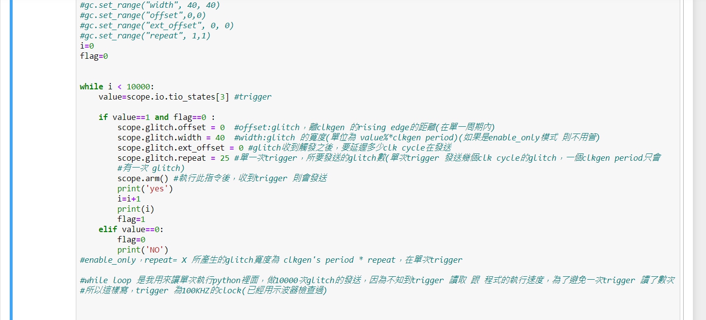
1,I set the 100KHz trigger(checked by oscilloscope),and the 1us glitch,but the module actually sand the glitch with about 200HZ…
2,I edit my python code, and it can work with “ext_single” and “trigger at specific frequency”,but I meet the problem above.
please ignore the annotations.
If you’re using ext_single, your glitch rate will be determined by how often you call scope.arm(), which won’t be much more than a few hundred times per second.
Alex