Thank you for solving my previous problems
I encounter the same problem:
1,I set the 100KHz trigger(checked by oscilloscope),and the 1us glitch,but the module actually sand the glitch with about 200HZ…
2,I edit my python code, and it can work with “ext_single” and “trigger at specific frequency”,but I meet the problem above.
If you’re using ext_single, your glitch rate will be determined by how often you call scope.arm(), which won’t be much more than a few hundred times per second.
@Alex_Dewar
How should I do in order to produce high frequency glitch(>1MHZ) with all parameters under my control?
However I can’t control the numbers of the glitch every “ext_continuous” happening, and I can’t use the “ext_single” to achieve high frequency glitch. T.T
I believe all the glitch settings have to go from Python to the FPGA since the glitch offset and width are changed via partial reconfiguration of the FPGA. You’ll need to choose between a high glitch frequency and being able to control the settings for each glitch.
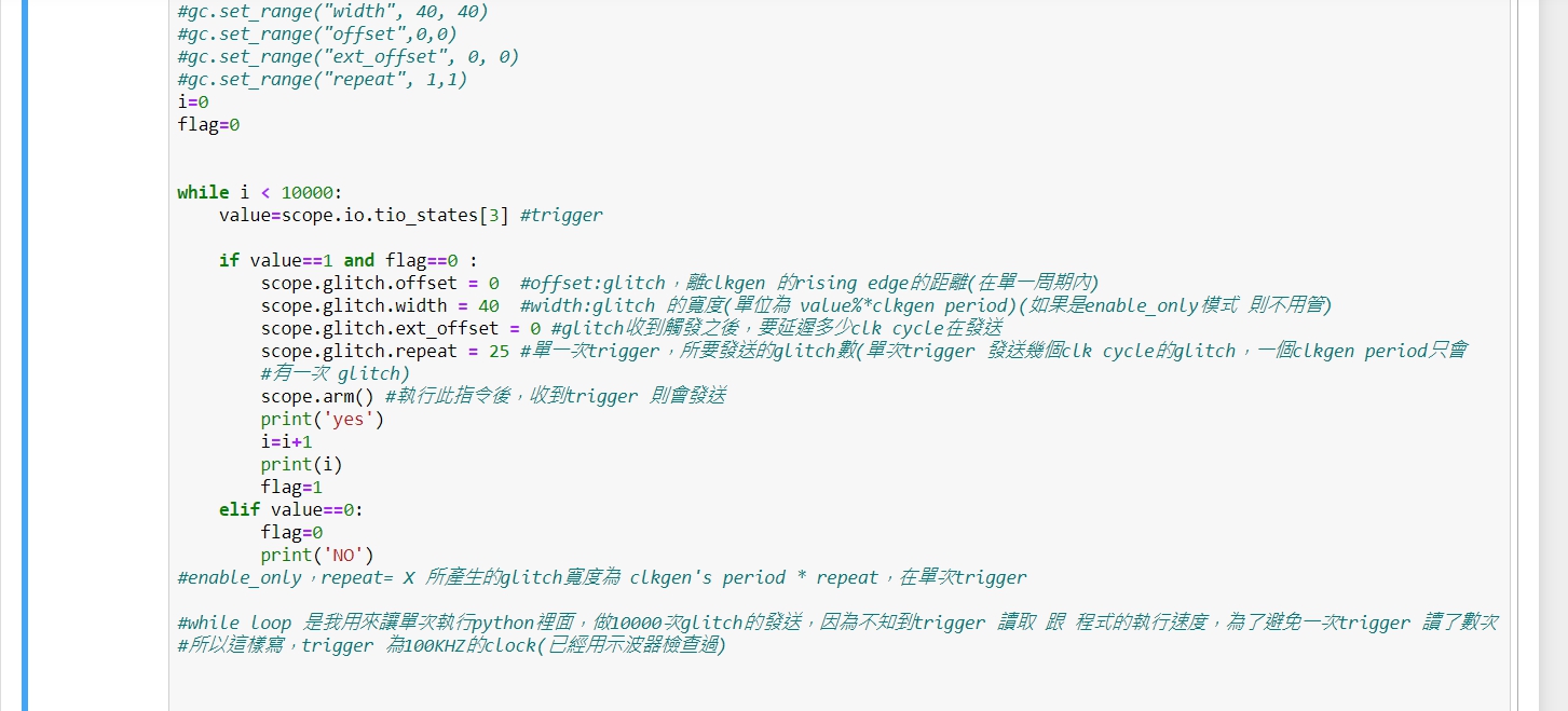
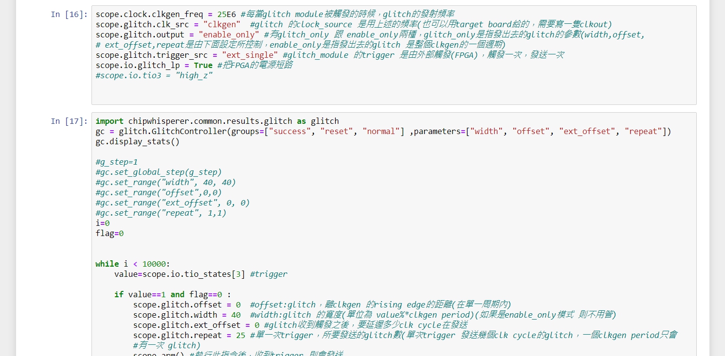
In recently, I try a lot of combination with my python code below. I find a few points:
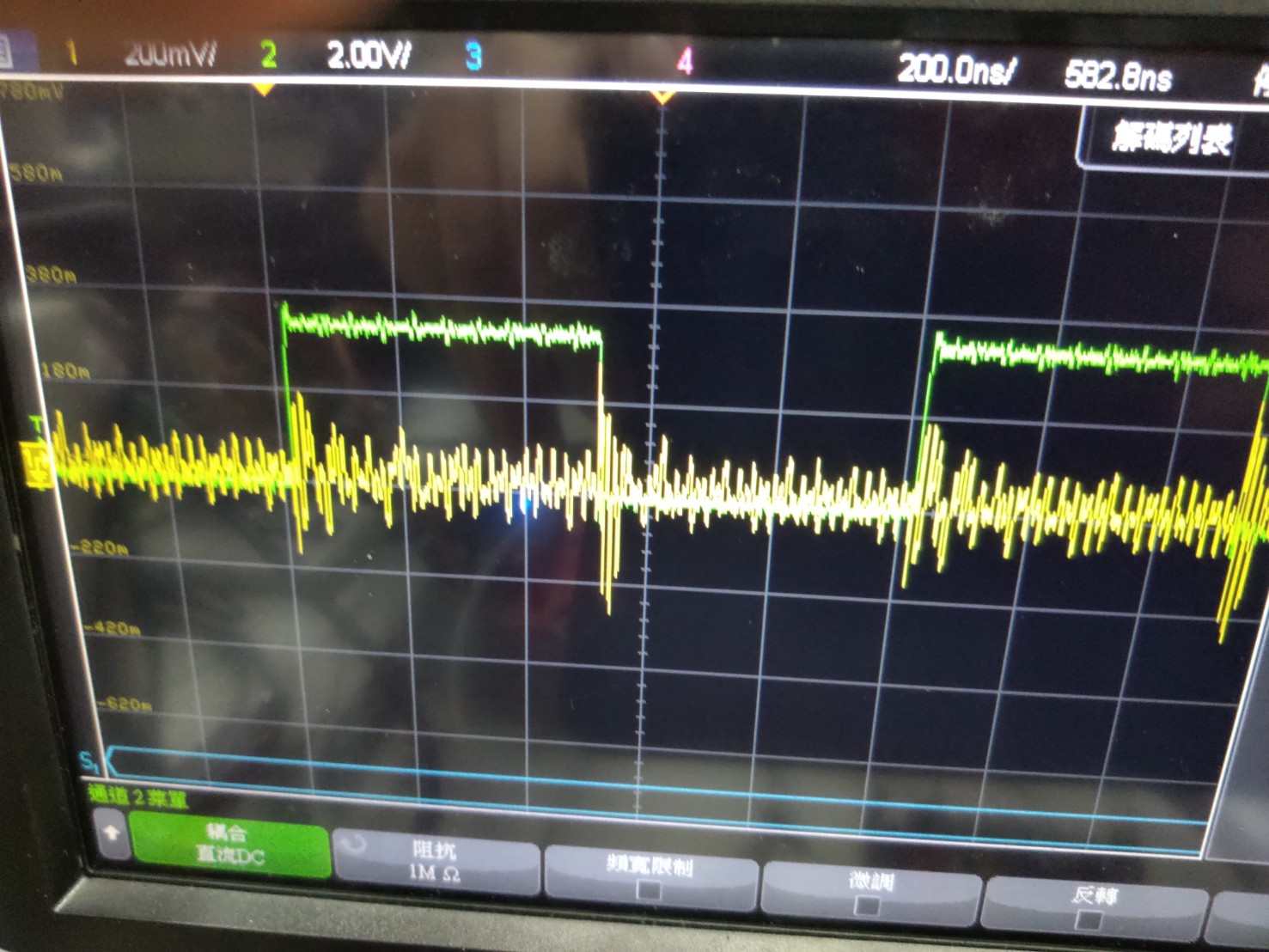
1,I can reach the high frequency glitch emitting(1Mhz~10MHz)(yellow line), but I had the positive glitch which wasn’t set by me in my falling edge of the trigger(green line). Why?
2,After I change the parameters(width , offset) , the power waveform on the oscilloscope didn’t any change. It changes only depend on the trigger frequency.Is it because the “scope.arm()” has the limited frequency to emit the glitch ,just like mentioned above by you?
3,How do you get the 500kHz+ glitch and trigger as you mentioned at 12/2?
I’m not too sure on this one, I’ll see if I can replicate this
I’m guessing the change is just too small for you to see (assuming you’re not using enable_only, which it doesn’t look like you are). I think it will be much easier to see the glitch if you change the power rail scope measurement to be DC coupled.
On the ChipWhisperer, I was using the ext_continuous setting. On the microcontroller side, I was just toggling a GPIO pin every few clock cycles.
HI @Alex_Dewar
I have some question:
1,Can I adjust the peak voltage/lowest voltage which the vcc glitch caused?
2,How many glitch did the “ext_continuous” actually did?
If you’re using enable_only, you can effectively control the width of the glitch using scope.glitch.repeat. Otherwise scope.glitch.width will control the width.
The glitch driver is just a MOSFET shorting the Vcc pin to ground though, so you won’t have much control over the shape of the glitch and how low/high it goes. You can play around with different SMA cable lengths to change the waveform a bit.
There’s no count on the Lite for this, so your best bet is to count the number of times the trigger pin went high via something an external counter.
Hi,@Alex_Dewar
The actual questions is that the Vcc glitch effects the Micro controller of the CW305?
I think it’s a key to help me solve my problems。
Thanks for your help!!
There’s lots of filtering before the shunt resistor, so the glitch won’t have much of an effect on the microcontroller. If you want to make sure, you can probe the Vcc pins of the microcontroller with your oscilloscope.