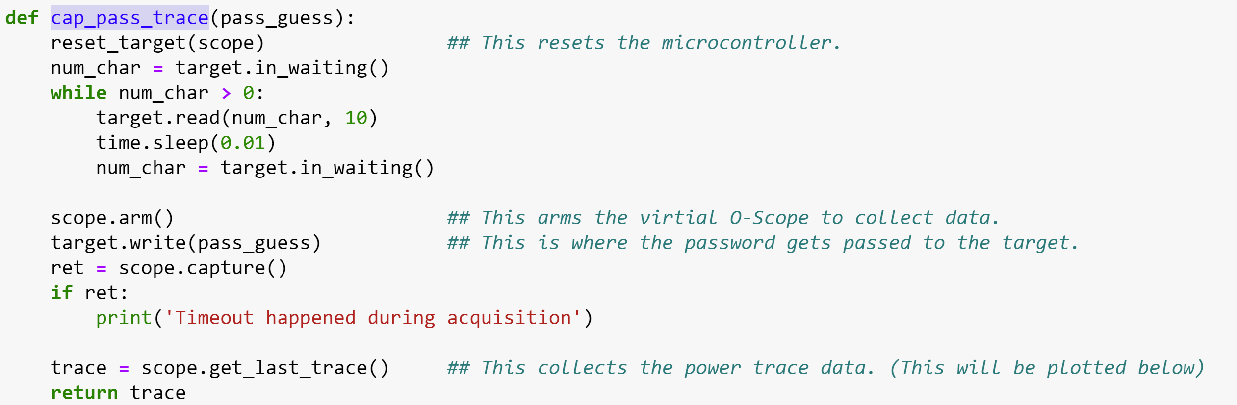
We are trying to measure the power signal that is use by OpenADC and the Password Trace function to uncover the password. The Password trace function is shown below.
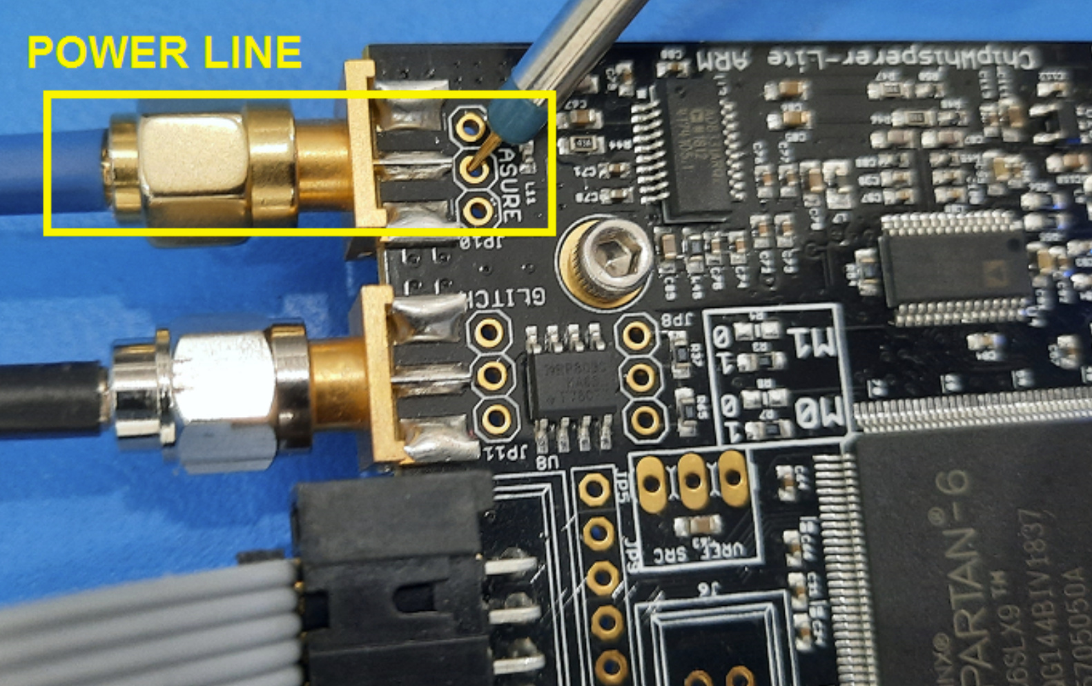
This uses the Scope object, which we examined in detail, but it was difficult to connect the code to the pins on the board. We assumed that the power line was being measured by the python code, so we stuck an O-scope probe there, See below.
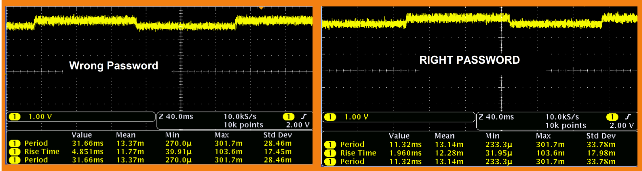
This is opposed to measuring the other ports on the driver board (IO1-io4, HS1, HS2). I still do not have a clear understanding of the data rolling across these lines in the case of a password response. In any case, it was difficult to see electrical differences between the right & wrong password in the power line data.
Where would you physically measure the electrical response to different passwords on the board? This is the same response used to uncover the password.
It appears that all the I/O (1-4) are inter changeable they can be used for inputs, outputs, ignored or used to send trigger signals. Is that correct? What are the differences between I/O and HS1 & HS2 pins?
The scope.arm function uses a trigger signal, which appears to synch the hardware to the python code. Where would I physically measure this on the board?
What if you follow the lab and measure using ChipWhisperer (instead of your oscilloscope)? In order to see the difference for the correct password, it’s crucial that the scope be triggered at the right time.
On the “measure” port.
Look at the documentation for scope.io: Deprecated API — ChipWhisperer 5.7.0 documentation
HS1 and HS2 are intended to be used as clocks, whereas IO1,2,3,4 are GPIOs. By default (see default_setup() in OpenADC.py), IO1/IO2 are UART, IO4 is the trigger, and HS2 is the clock that’s generated by the capture board and fed to the target.
By default, IO4. (which is also available on the unsoldered 10-pin header that’s right next to the 20-pin cable connector)
It sounds like you want to really understand the nuts and bolts of ChipWhisperer. My advice is to make your way through all the labs, and don’t be afraid to really dive into the CW code. Best arm yourself with a good Python IDE (or if you’re an old-timer like me, find and grep will help you make your way).
If you want it to be! (I don’t think any of our labs use it as a trigger.)
The trigger can be a combination of the GPIOs. Normally we just use IO4, but if you have different requirements, the capability and flexibility is there for you.
Again, read the scope.trigger section of https://chipwhisperer.readthedocs.io/en/latest/api.html#scope
I know there is a lot of info to wade through, but it (should be!) all there.