CW-Lite VCC glitching unexpected behaviour

Hi everyone,

I’ve recently purchased a CW-Lite 2-part version from Mouser and have been experimenting with it for a little under a week, doing some of the glitching tutorials. I’ve hooked up some kind of Chinese Arduino Nano clone (ATMEGA328P) to play around with glitching that platform.

I seem to have run into an issue or two, not completely sure if it’s software, hardware or human. I’ve found that VCC glitching has been difficult and quite unreliable, and have done some troubleshooting tonight to try and see what was happening to VCC on the target when the glitches were triggered.

I’ve got two concerns. Firstly, the glitches never seem to pull VCC below about 1.8V or so. I was expecting that they would pull it down closer to 0V. I’ve got a 47R resistor in series with the 3.3V supply from the CW-Lite. I’ve probed the voltages during glitching at the CW side (centre pin of the GLITCH connector), also checked it at one of the AVR IC VCC pins, to rule out a bad connection. The resistance between the +3.3V pin on the 20-pin header on the CW-Lite to the centre pin of the GLITCH SMA connector is about 47R1, so the hardware setup seems fine to me.

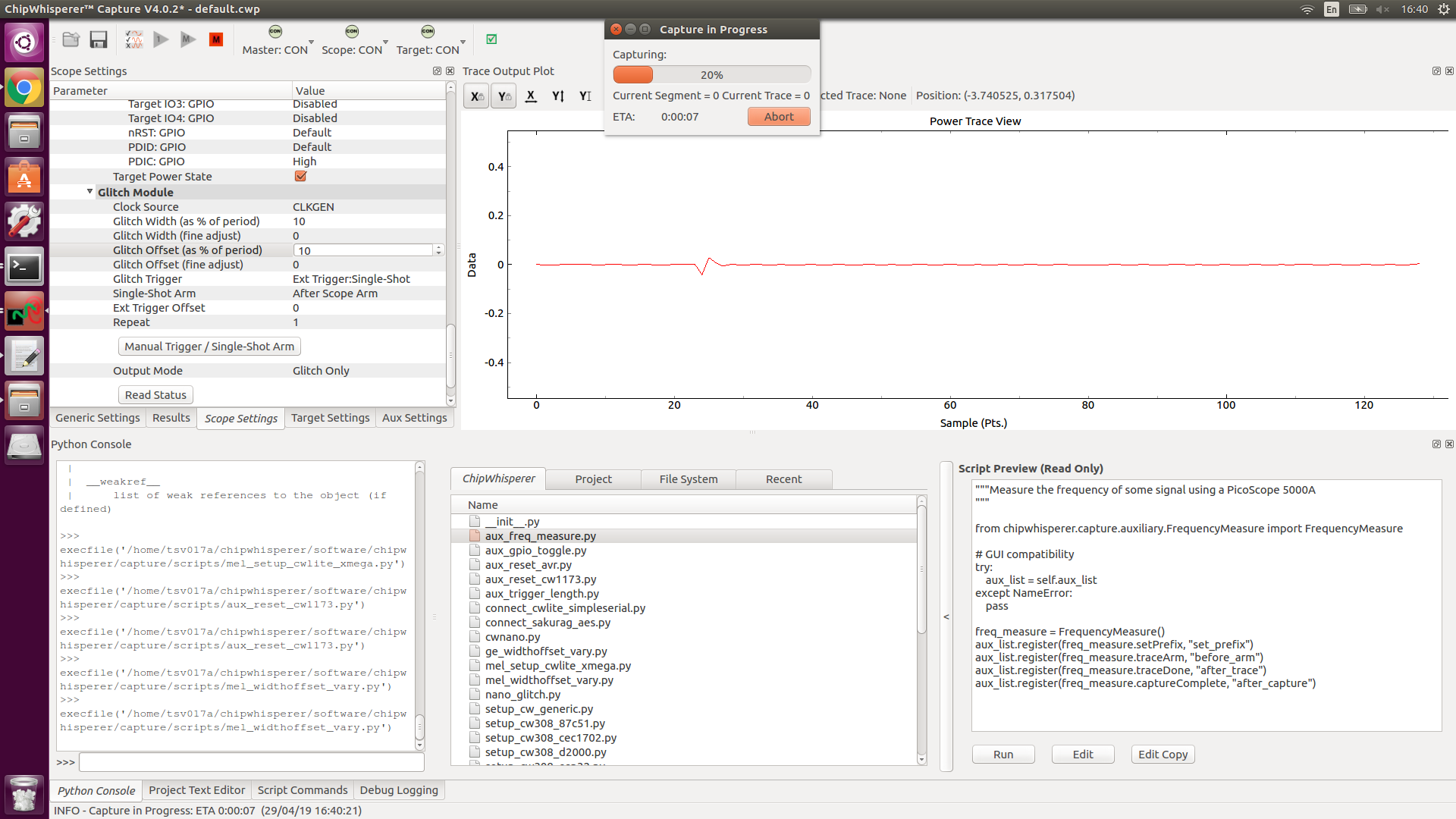
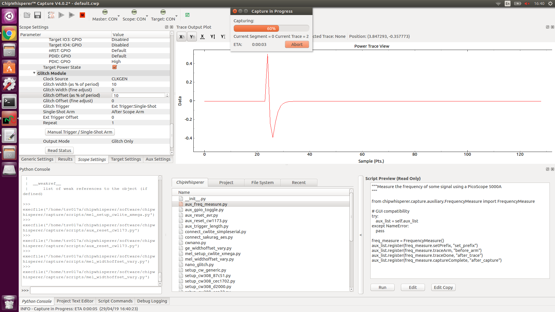
The second issue which I feel is probably more important, is that when I manually trigger a glitch, I can see for example 100 repeats of the glitch, but if I set the software to Ext Trigger:Single Shot and then run a Capture 1, it only seems to fire the glitch once, as if the “Repeat” setting is being ignored.

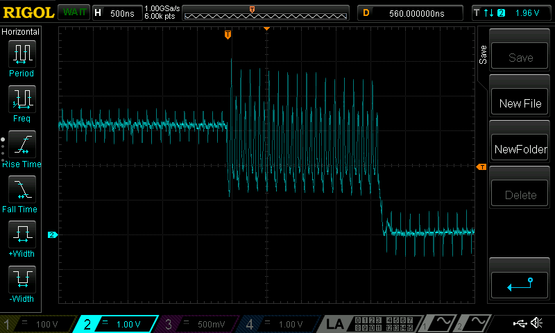
I’ve uploaded some 'scope screenshots:
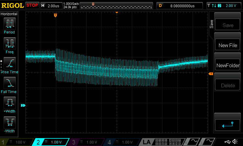
NewFile1:
Glitch Trigger = MANUAL
Pressed “Manual Trigger / Single-Shot Arm” button. Recorded resulting glitch:
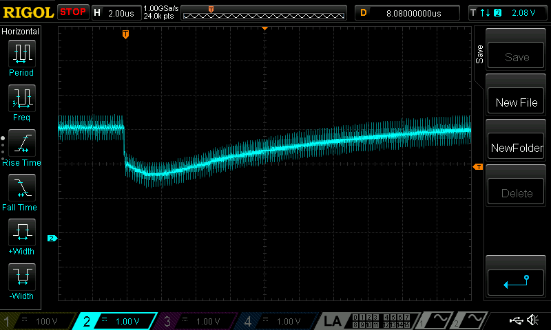
NewFile2:
Glitch Trigger = Ext Trigger:Single-Shot
Ran “Capture 1” and recorded the resulting glitch:

Settings:

scope
cwlite Device
gain =
mode = low
gain = 40
db = 19.28125
adc =
state = False
basic_mode = rising_edge
timeout = 2
offset = 0
presamples = 0
samples = 1000
decimate = 1
trig_count = 8
clock =
adc_src = clkgen_x4
adc_phase = 0
adc_freq = 29538459
adc_rate = 29538459
adc_locked = True
freq_ctr = 7384609
freq_ctr_src = extclk
clkgen_src = system
extclk_freq = 10000000
clkgen_mul = 2
clkgen_div = 26
clkgen_freq = 7384615
clkgen_locked = True
trigger =
triggers = tio4
module = basic
io =
tio1 = serial_tx
tio2 = serial_rx
tio3 = high_z
tio4 = high_z
pdid = high_z
pdic = high
nrst = high_z
glitch_hp = True
glitch_lp = False
extclk_src = hs1
hs2 = clkgen
target_pwr = True
glitch =
clk_src = clkgen
width = 48.828125
width_fine = 0
offset = 0.0
offset_fine = -49
trigger_src = ext_single
arm_timing = after_scope
ext_offset = 0
repeat = 100
output = glitch_only

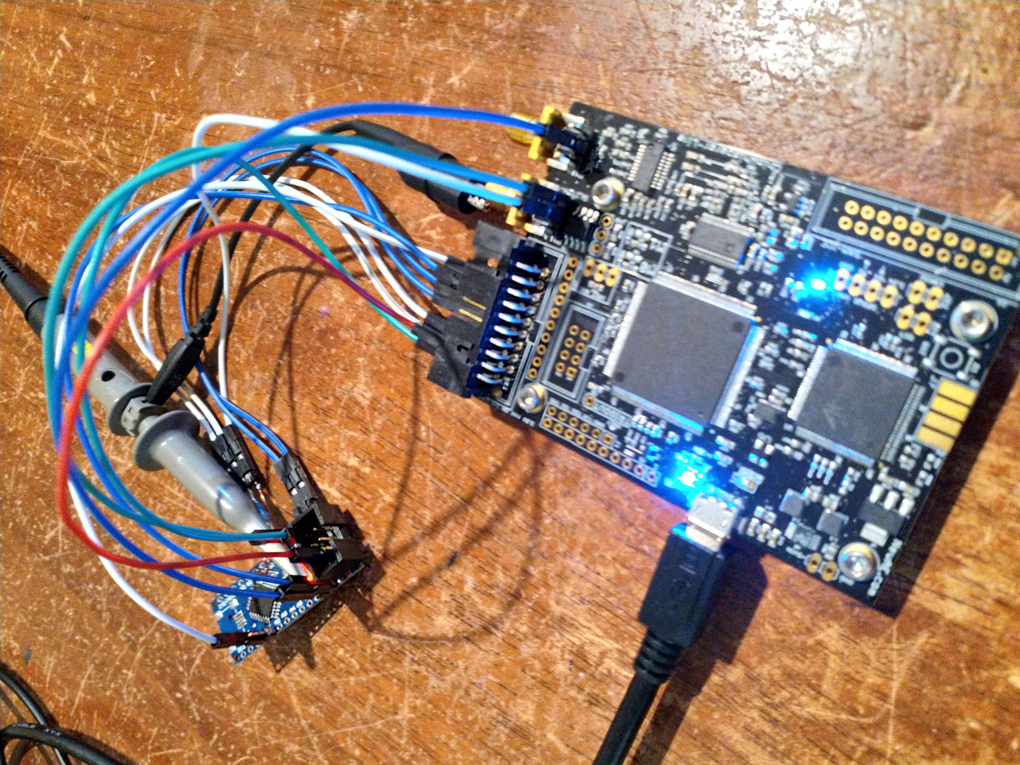
The target hardware is a modified eBay Arduino Nano clone PCB, as mentioned. All capacitors have been removed as well as other components, other than a 100nF capacitor from RESET to GND. I’ve connected a 47R resistor in series with +3.3V from the CW-Lite, the GLITCH line is connected to the AVR VCC. I’ve used the NOTDuino schematic as a reference when hooking it up.

I’d like to know why the glitch behaviour is changing between manual glitching and using an external trigger. I’m using the CW VMware image and have done a git pull to update the software.

Any help/advice would be appreciated.

Regards,
Rob.

HS-Glitch Out Enable (High Power): Disabled
HS-Glitch Out Enable (Low Power): Enabled
Glitch Trigger: Manual
Output Mode: Enable Only
Repeat: 100

The above settings briefly pull VCC down to 0V when the “Manual Trigger / Single-Shot Arm” button is pressed.

However, changing “Glitch Trigger” to “Ext Trigger:Single-Shot” and pressing “Capture 1” (or Capture M) results in a different glitch:

I’ve found that setting “Glitch Trigger” to manual, then pressing “Capture 1” or “Capture M” results in reliable glitch insertion, but I thought that wasn’t supposed to work?

Hi Rob,

That is strange behaviour. Things are a little busy right now, but I’ll look into it when I have time.

I was able to do some glitching a few weeks ago for tutorial A9 which uses enable only on an external board, so I’d try using that with a low repeat (say 1 or 2). Enable only I believe pulls Vcc low for an entire clock cycle, so large repeats usually just end up resetting the target. That also means that regular offset/width don’t affect it.

Alex

Hi Alex,

Thanks for the response. I’m only using 100 repeats to make it really obvious when it’s working or not for the purpose of monitoring it on the scope. I’m not worried about what the target is doing (it is resetting, as you suggested).

I was trying to sort out this issue last night. For no apparent reason, I managed to get the glitching to work correctly with Glitch Only and Ext Trigger:Single-Shot. I got a successful glitch while it was working with Glitch Only last night, but on occasion (3 times) the glitch would be done and at the end of the glitch, the MOSFET would stay on, keeping VCC at 0V. The software continued on like everything was fine, thinking it was still inserting glitches when the MOSFET was stuck on. To revive it, I had to uncheck (disable) and then re-enable the “HS-Glitch Out Enable (Low Power)” option. I was doing 1000 traces with Capture M at the time, with the MOSFET getting stuck on about once every 300-400 traces on average (it seems random).

I have no idea why the glitching started to work last night, I plan to look into it further shortly.

Regards,
Rob.

Just an update, the CW-Lite has been behaving today for the most part. I’m not sure why it’s working now and wasn’t earlier. I also think I know what was happening in my last scope trace where the voltage sharply dipped to about 2.1V and then recovered. There was a ceramic cap connected from VCC to RESET on the target board, and I think that when the reset script I’d set up in the CW software pulled the reset line low, that the cap would charge through the 47 ohm resistor that’s in series with the 3.3V from the CW-Lite, briefly pulling down the voltage on the target board. I removed the capacitor and replaced it with a 1K resistor instead, which seems to have fixed that.

I’m still getting problems with the glitching MOSFET getting stuck on occasionally. I don’t know if it would make any difference, but during most of the day I’ve been doing glitches with positive glitch width values but then finished doing those and started doing some with negative glitch width values. The MOSFET started getting stuck on when I started doing the negative glitch width glitches but it didn’t happen when I was doing the positive glitch width glitches. Not sure if that’s just coincidence or if it means anything. I’m using the low power MOSFET, doing VCC glitching.

Here’s a scope trace showing what happens to VCC when the MOSFET is stuck on. Toggling the “HS-Glitch Out Enable (Low Power)” checkbox in the software will return it to normal. I’ve done nearly 3000 traces, the MOSFET has become stuck on about 6 times so far during that batch of 3000. The CW software is set to do 16 repeats of the glitch.

Settings when one of the failures happened and the MOSFET got stuck on:

glitch =
clk_src = clkgen
width = -14.453125
width_fine = 0
offset = 13.671875
offset_fine = 0
trigger_src = ext_single
arm_timing = after_scope
ext_offset = 8
repeat = 16
output = glitch_only

Hi Rob,

The FET staying stuck on is a known issue, but unfortunately the cause has been pretty hard to track down.

You could probably work around this by resetting this value after every capture via an aux module. I can’t remember what the python value is off the top of my head, but you should be able to find it by running help(scope.io).

Alex

Hi,

I have also experienced difficulties with VCC glitching and am familiar with the stuck MOSFET. I have not found the root cause but once I started using the UFO board (with external power) this problem disappeared. It definitely looked to me as if the CW was glitching itself.

Two(3) more things:

you have the external offset set to 0 . this would glitch at the moment the trigger happens is this what you want?

The screenshots look different from what I am used to see. In my experiments the repeated glitch caused a slower decay of the voltage and the actual glitch was happening after the glitch repeat (e.g. on the opposite voltage).
I don’t have a screen shot ready but …drawn something. How long are your wires to the target?

What version of CW are you using?

Hi ExMachina,

I took Alex’s hint about resetting the glitch setting, I wrote a python script that seems to be working, so while I see the MOSFET get stuck on occasionally, it’s now fixing itself.

To answer your questions:

  1. Regarding having external offset set to zero, I’m playing with the glitch-simple firmware and calling glitch1() from main(). The glitch trigger happens in the firmware just prior to the while loop that’s the target of the glitch, so a zero offset or something small seems fairly appropriate to me. That said, I’m just learning so happy to be corrected.

  2. I couldn’t view your drawing, but the wires are about 200mm long (about 8") and not of great quality, not a lot of copper in them. There are two grounds and one 3.3V supply from the CW-Lite board. There’s a power LED on the target that’s always on, so that might explain why the decay is apparently faster. Also, there’s only about 100nF of capacitance on the target board at the moment (just one 100nF capacitor between the AVR’s VCC and GND pins). The resistor in series with the 3.3V from the CW-Lite is 47 ohms.

  3. Not sure if you mean software or hardware, software is a git pull from the github repo, develop branch, last pull was a couple of days ago. The hardware I’m using is a CW-Lite 2-part version (the PCB says P/N: NPCB-CWLITE-04, model CW1173) with my own target (ATmega328P duino Nano clone with the extra parts like the USB<>Serial IC removed so that it is basically just the AVR, a 47 ohm resistor, a 1K resistor (reset pull-up) and a 100nF cap).

This is the setup:

Regards,
Rob.

Hi Rob,

I’m trying out the Tutorial A3 VCC Glitch Attacks and I’m experiencing some difficulties in getting it to work.
I also did a loop back and observed weird patterns in the glitches, e.g. inconsistent VCC patterns.
Could you share a little more about the python script and the variable that you used to reset the chipwhisperer or the glitch module?

Thanks.

Regards,
Melvin.

Hi Melvin,

I believe this is the script that I ended up with to stop the MOSFET from getting stuck on. If it doesn’t work (it needs to be loaded in the aux section from memory) let me know. It’s been a long time (about 6 months) since I played around with the ChipWhisperer software/hardware.

"""Toggle glitch GPIO lines
Used to toggle the glitch MOSFET GPIO lines off/on as a work-around for a
bug that occasionally causes the glitch MOSFET to remain on after a VCC
glitch has occurred.
"""

# GUI compatibility
try:
    aux_list = self.aux_list
except NameError:
    pass


class TGL(object):
        def toggle_glitch_hp(self, scope, target, project):
                scope.io.cwe.setTargetGlitchOut('A', False)
                scope.io.cwe.setTargetGlitchOut('A', True)

        def toggle_glitch_lp(self, scope, target, project):
                scope.io.cwe.setTargetGlitchOut('B', False)
                scope.io.cwe.setTargetGlitchOut('B', True)


x = TGL()
aux_list.register(x.toggle_glitch_lp, "after_trace")

Regards,
Rob.

Hi Rob,

Thanks for the prompt response.
Let me give it a shot. Did you manage to perform VCC glitching on the XMEGA CW303 target? Could you share the successful glitch parameters?

Meanwhile, I have another question.
I observed that the VCC glitch module has some “rise time” issue. It takes a few attempts at the same glitch parameters to achieve the desired glitch pattern. For example, when I capture the same glitch width and offset values (both at 10) for 5 times, the 1st captured waveform is almost flat, the 2nd shows very minute spikes, the 3rd shows a high positive spike, the 4th shows a huge negative pull, and the 5th looks normal. This happens particularly when it crosses 0. Any idea why is this happening and how I may resolve it?

Thanks.

Regards,
Melvin.

Hi Melvin,

I did manage to get the glitching working on the target that came with my CW1173 (XMEGA, but not sure if that’s a CW303 or not - I can’t remember).

I no longer have my notes about what worked, though just skimming back over tutorial A2, I remember it saying that positive glitch offsets seem to work better, though I’m sure that in my case it was negative offsets that worked better, but nothing worked well or reliably. About the best I managed to achieve was 3-4 out of 10 glitches working and I’m fairly sure I was clock glitching at that stage and had more or less given up on VCC glitching.

Regards,
Rob.

YMjIK Hello all the problem is uart cwlite only support 3.3v serial data and your target use 5v uart and trigout you need connected to rst pin from your victims.