from tqdm import tnrange
import numpy as np
import time
from Crypto.Cipher import AES

ktp = cw.ktp.Basic()

traces = []
textin = []
keys = []
N = 50  # Number of traces
S = 250 # Number of sets

# initialize cipher to verify DUT result:
key, text = ktp.next()
cipher = AES.new(bytes(key), AES.MODE_ECB)

for j in tnrange(S, desc='Set Number'):
    tries = 100
    scope.clock.adc_phase = j #Update the phase
    for i in range(tries):
        scope.clock.reset_adc()
        time.sleep(0.1)
        if scope.clock.adc_locked:
            break
    if not scope.clock.adc_locked:
        print("Couldn't lock")
    time.sleep(3)
    for i in tnrange(N, desc='Capturing traces'):
        #key, text = ktp.next()  # Key and text is not updated
        textin.append(text)
        keys.append(key)

        ret = cw.capture_trace(scope, target, text, key)
        if not ret:
            print("Failed capture")
            continue

        assert (list(ret.textout) == list(cipher.encrypt(bytes(text)))), "Incorrect encryption result!\nGot {}\nExp {}\n".format(ret.textout, list(text))
        #trace += scope.getLastTrace()

        traces.append(ret.wave)
        project.traces.append(ret)
I ran this code above which takes 50 traces for 250 different phase settings.
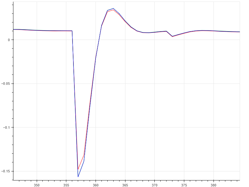
I took 50 traces for 250 different phases and averaged them by phase, resulting in 250 different traces. I then took the power of each of these average traces and plotted them to see if there was any noticeable trend. Maybe I am not sampling enough traces per phase setting or my methodology is incorrect but it doesn’t seem like the phase is actually changing.
Yeah, that code there seems to break adc_phase for some reason. If I adjust adc_phase right after connecting, I can see the phase change between the ADC clock and the target clock, but if I run that code, then try to change the phase, it doesn’t update. I’ll do some more investigating and will let you know if I figure this out.
EDIT: Try removing the scope.clock.reset_adc(). It seems like calling that in that context breaks ADC phase for some reason
EDIT: I removed it, but also instead of taking the area underneath the curve, I just take the peak value of one round of AES(10th round specifically). There does seem to be a trend as the phase increases but I’ll try to collect more samples for something more statistically significant.
Not sure what effect ADC phase has on that data, but if you want to verify the phase change, you can measure the target clock on HS2 and the ADC clock on R54 (right above U4, which is the ADC).
Also, feel free to share once you’re done running through all the data. I’m guessing you’re trying to find the most effective phase offset without running through a full CPA attack?
Can they be measured in the chipwhisperer software? I’m guessing you are using some oscilloscope? Currently, an oscilloscope is not accessible to me at the moment which is why I’m relying on the data.
EDIT: Id be happy to share the data once its done being collected. Basically, I’m just looking to see which phase offset yields a measurement with the most power consumed and assuming this to be the phase offset most effective for CPA
Yeah, I’m using an oscilloscope. You might be able to measure the phase offset using the FPGA (we do something similar with the glitch module on the Husky), but we don’t have any plans to implement this on the Lite.
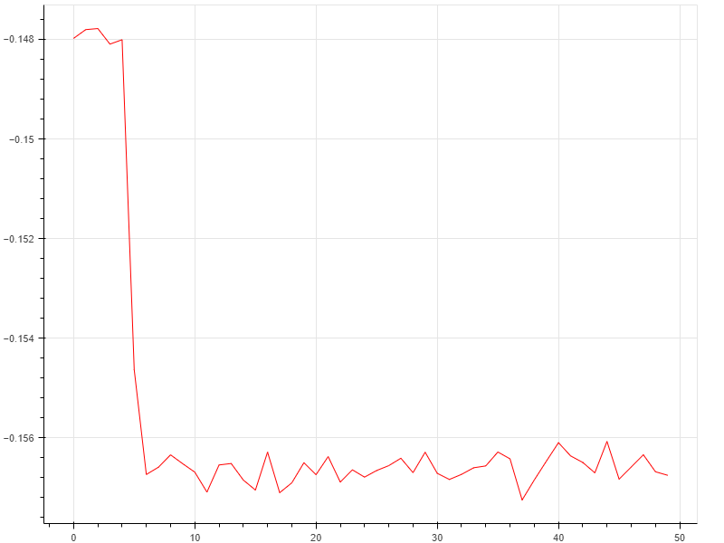
This is what I got by using the software to detect for the best offset. y-axis is power, x axis is the integer phase offset divided by 5, total of 50 different phases tested. 500 traces per phase. Id conclude from this that the phase is indeed changing so I’m guessing your oscilloscope was showing the phase changing as well.