Adventures with the ChipSHOUTER and ChipWhisperer External Trigger

I’ve spent the last couple weeks playing with the ChipSHOUTER and understanding how it works. My setup mounts the 1mm CCW probe tip over a 12" SMA hose (I know it’s preferred to mount the Shouter directly… But it seems to work OK!) onto an XY positioner and connects up to an Ubuntu host machine. I was able to see results without issue with the Simple EMFI and Ballistic Gel DUTs by manually triggering the EM pulse, either with the convenient big red button or through the microcontroller API.

This all went well, but progressing further quickly revealed a significant difficulty spike. In order to inject a pulse on-demand in response to a stimulus, one must use a ChipWhisperer. This first forced me to learn how my ChipWhisperer Lite works, but with the strong tutorials in place I managed to figure out how to proceed after a couple days. My DUT pulls a GPIO pin high, sleeps for 2us, and then enters the typical “acc = 0; for i < 500; for j < 500; acc += 1” loop associated with EMFI testing. The ChipWhisperer looks for this pin on TIO4, and triggers accordingly.

My understanding of the design of the ChipSHOUTER is that it is a teaching and analysis platform first, and a fault injection system second. It teaches you the principles of EMFI by showing you how it reacts to DUTs. It can also characterize faults on a platform with simple scripting. But in practice, the microcontroller is not helpful when mounting an actual EMFI attack, since it cannot respond to external stimuli other than the Python API and the big red button. I can’t remember where this was written, but Colin O’Flynn said somewhere that 80% of his actual ChipSHOUTER usage was with a ChipWhisperer attached. That’s why I’m taking the ChipWhisperer approach-- it seems to be the way, by design, to perform a useful EMFI attack, at the cost of giving up the useful learning features.

So with my setup and methodology hopefully explained well enough, allow me to introduce my problem: I have very little control over the width of the pulse injected. By connecting the external trigger signal to the ChipWhisperers “glitch” signal with the included SMA cable (exactly as shown in Figure 4 of MIN()imum Failure: EMFI Attacks against USB Stacks) I can observe a pulse of no shorter than 750ns. This pulse is extremely powerful and effective, managing to corrupt most registers on my DUT to the same random value and therefore cause exceptions, but I want subtler results like a simple incorrect addition. I can increase the length of the pulse by increasing scope.glitch.repeat but cannot shorten it below a value of 1. Note that I can observe pulses of the same length by manually triggering the Shouter with a 750ns width (i.e. going through the microcontroller.)

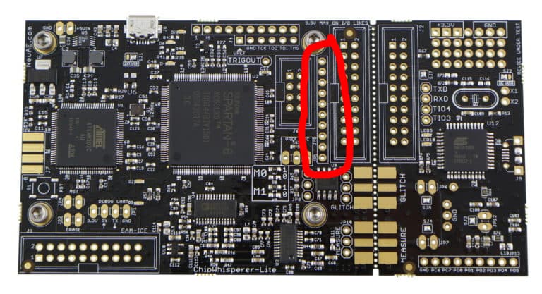
This forum post seems to have a similar problem to my own to a less extreme extent. It suggests using the HS2 signal on the advanced breakout board. Now, I do have this advanced breakout board, but I don’t yet have the connector on the ChipWhisperer Lite to connect it-- that’ll be arriving tomorrow in the mail-- so I jerry-rigged a way to attach an SMA connection to the alternate breakout HS2 breakout point on the row of connections behind the main connector which I have soldered some headers on to. (Specifically, I used an oscilloscope probe at 10X attenuation and an adapter.)

This worked for a short period of time-- I was able to pulse at around 90ns granularity or so (that is, 90ns pulse width, 180ns and so on.) However, after two hours, the Shouter started emitting faults whenever I attempted to pulse, and after that time it would simply either fault the moment I attached the HS2 connection or do nothing at all when pulsing.

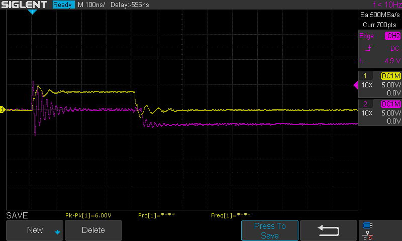
This is a picture of the signals I receive from A. the glitch signal and B. the HS2 signal. Something is clearly up with that glitch signal, but the HS2 signal looks OK. At this point, I’m at a loss as to how to proceed-- The ChipWhisperer can’t seem to make the ChipSHOUTER happy in any of the cases I present it. I must be doing something wildly wrong here.

Here is the code I’m using to test pulses being sent.

from chipshouter import ChipSHOUTER
import chipwhisperer as cw
import time

cs = ChipSHOUTER('/dev/ttyUSB0')
# Setup for manual trigger per the docs
cs.hwtrig_mode = 0
cs.hwtrig_term = 0
if not cs.armed:
    cs.armed = True
    time.sleep(2)

scope = cw.scope()
scope.default_setup()

scope.glitch.output = 'enable_only'
scope.glitch.clk_src = "clkgen"
scope.io.hs2 = "glitch"
scope.glitch.width = 2
scope.glitch.repeat = 1
scope.glitch.trigger_src = 'manual'
scope.io.glitch_lp = True
scope.arm()

while True:
    res = input("Glitch: ")
    if res == '':
        pass
    elif res == 'w':
        scope.glitch.width = int(input('a'))
    else:
        scope.glitch.repeat = int(res)
    scope.glitch.manual_trigger()

Hi,

If you mean that you device is connected to your XY table via the probe tip, I strongly recommend that you instead mount it via the case of the device. The probe isn’t meant to be under mechanical strain like this This can permanently damage your device and is a safety hazard.

One thing you might be running into here is that oscilloscope probe has quite a high impedance - you should see much better results with the HS2 output and the ChipSHOUTER input at 50ohms like with an SMB to SMA connector. The ChipSHOUTER kit should actually come with one of these.

Do you know what fault you’re getting? If you’re getting a fault whenever you attach your trigger, I’m guessing it’s a trigger issue. This is usually caused by attaching an active trigger (i.e. you have the ChipSHOUTER set to active low and you attach a trigger that is already low).

Is your purple signal the voltage/current glitching from the ChipSHOUTER?

Looking at your code, it looks like you’ve got the ChipSHOUTER set to an active low (cs.hwtrig_mode = 0) high impedance (cw.hwtrig_term = 0) trigger. You probably want the opposite with your final setup (both set to 1). Also, I don’t think this will affect things, but you can leave out turning the glitch mosfets on (scope.io.glitch_lp).

Alex

That isn’t what I mean-- My setup is pretty similar to this mounting table wherein it has a cable between the Shouter and the probe.

This is a good call. As aforementioned, I can’t use the breakout board since the necessary connector hasn’t arrived yet for me to solder it on, so I’m bringing out the signal on this header:

One of the things I had tried previously was using a direct connection like the one shown in this image to connect up the signal to the Shouter, but that immediately faulted…

Until I set the trigger to “active high”, when things started immediately working like they had before! I’ve no clue why it worked in the first place but those two insights made it right.

No, that purple signal is the output from the “glitch” SMA signal on the ChipWhisperer. I’m not sure, but I don’t think it should be oscillating like that… That might be why I see such long pulses when using it.

These things are what the ChipSHOUTER manual says to do on page 26. Why do you suggest I do the opposite? I’ll admit that I blindly set them as suggested without thinking too much.

So from here, I’ll be able to start experimenting again, but do you have suggestions for how I can further increase my pulse granularity? With this HS2 line, I lose the ability to control the clock of the target should I need to do that and I also only get increments of ~90ns. It seems like I should be able to pulse with more detail than that given that the microcontroller can do so, and ideally I’d do so with the glitch line so that HS2 can be left to its original purpose.

Ah alright, that should be no problem then.

IIRC the pull up on the active low/high-z is like 10kohms, so with the scope probe being ~10Mohms, that probably caused some issues.

The MOSFET method of triggering isn’t great (you’re just pulling down a 10k pullup, then releasing it), so I’m not too surprised the glitch signal doesn’t look great. Honestly, you’ll probably get different waveforms depending on where you measure (near the ChipWhisperer vs. near the ChipSHOUTER)

The active-low/high-impedance is required for the glitch port to work with the ChipSHOUTER. If you look at the diagram on page 26, you can see that the glitch port is high-z when the glitch is inactive and ground when it is active, which is called open-drain. The pull up R_pu is only present when active low and high impedance. If it wasn’t there (in any other combination of mode/term), your trigger would be floating and the glitch transistor wouldn’t work. The HS2 glitch output is push-pull, so 3.3V/ground are the two states instead of high-z/ground, so you don’t have this same requirement.

The termination mode is for better impedance matching, which will lower the effect of reflections on the trigger line between the ChipWhisperer and the ChipSHOUTER.

If that’s just generally the case, I find it odd that people have managed to get results with this approach at all, let alone it being the suggested method in the documentation and having a success case in academic papers. Could there be something else going on? I’m still confused about how to increase my level of granularity and hopefully bring it closer to the base microcontroller.

To make sure I’m understanding this right: If you use the HS2 port, you need to set the following parameters in the ChipSHOUTER:

cs.hwtrig_mode = 1
cs.hwtrig_term = 1

and you do NOT need to enable the glitch_lp MOSFET. Correct?

Things probably look different based on where you measure - this isn’t a well matched signal. Also, a small correction - the recommended method in the datasheet is to use the HS2 OUT connector with the advanced breakout board. This is just provided as an alternative to people without the CW506.

I’m a little confused by your setup - the cable you use to connect the CW506 and the glitch port on the ChipWhisperer should be the same (SMA to SMB).

Not being able to clock the target at the same time is unfortunately a limitation of the ChipWhisperer-Lite, not really much you can do about that. The later ChipWhisperer-Pro and ChipWhisperer-Husky have an extra glitch out port that can be used instead.

You can increase the resolution of your glitch by increasing scope.clock.clkgen_freq. enable_only glitches a full clock cycle of this clock, so if you increase this frequency, you’ll decrease the amount of time you glitch. You can set it to something like 100MHz, then use various scope.glitch.repeat to control the glitch width. Note that scope.glitch.width doesn’t do anything in enable_only mode.

Yup, that’s correct.

Alex