hi all, does anyone have experience with what is capable with the ATSAMD21 aka CW308T_ATSAMR21. I have been experimenting with voltage glitching to bypass the security bit on startup in order to access the devices memory with jlink/swd. So far without much success. Its my first CW project and have been glitching the vddcore triggered by power up - various positions and widths etc.
Does anyone else have experience with the D21 or D20 and know if voltage glitching is possible on this target or have a better strategy for accessing memory.
Intellectual Property Protection
Intellectual property protection consists of restricting access to internal memories from external tools when the device
is protected, and this is accomplished by setting the NVMCTRL security bit. This protected state can be removed
by issuing a Chip-Erase (refer to 13.7 Chip Erase). When the device is protected, read/write accesses using the
AHB-AP are limited to the DSU address range and DSU commands are restricted. When issuing a Chip-Erase,
sensitive information is erased from volatile memory and Flash.
If yes, I would collect the power traces for the sample where the NVMCTRL bit is not set and then for the protected sample. Comparing the traces collected from protected and non-protected devices gives you a clue where to find the exact location of checking the NVMCTRL bit.
This place will be your target to glitch!
Thanks - yes took samples from two clean ATSAMD21’s, one with the bit set and the other without, giving a small clue but after a few days of glitching in the area with a width of 40 hasn’t yielded results on the locked version. So I was trying to determine if the BOD is an effective blocker on this IC and then I would move onto another method with the bootloader glitch. Appreciate your response.
Could you describe more what you did and how?
Did you control by oscilloscope the VCC glitch happens? You should control it as close as possible to the VCC pin on the SoC.
Also you should sync the event (checking of the NVMCTRL bit) and glitch. Try to use different glitch offset relative to the event.
BTW, do you use the coax cable to glitch? From my experience, the coax cable attenuate signals significantly and I did special devices based on the SMA connector to get rid of coax cable.
Setup is a breakout board with the ATSAMD21 in a QFN package, similar to the CW308T_ATSAMR21. CW Lite (but have a Husky to try also) and have CW VCC 3.3 to target VCC, have coax cable soldered to landing pad and ground next to VCC_Core (1.2v). Have an sma T connecting the scope and CW. Segger Jlink on SWD with NRST connected CW (not jlink).
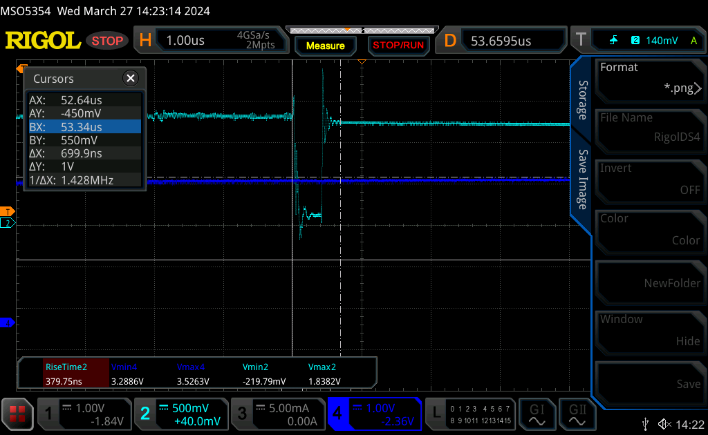
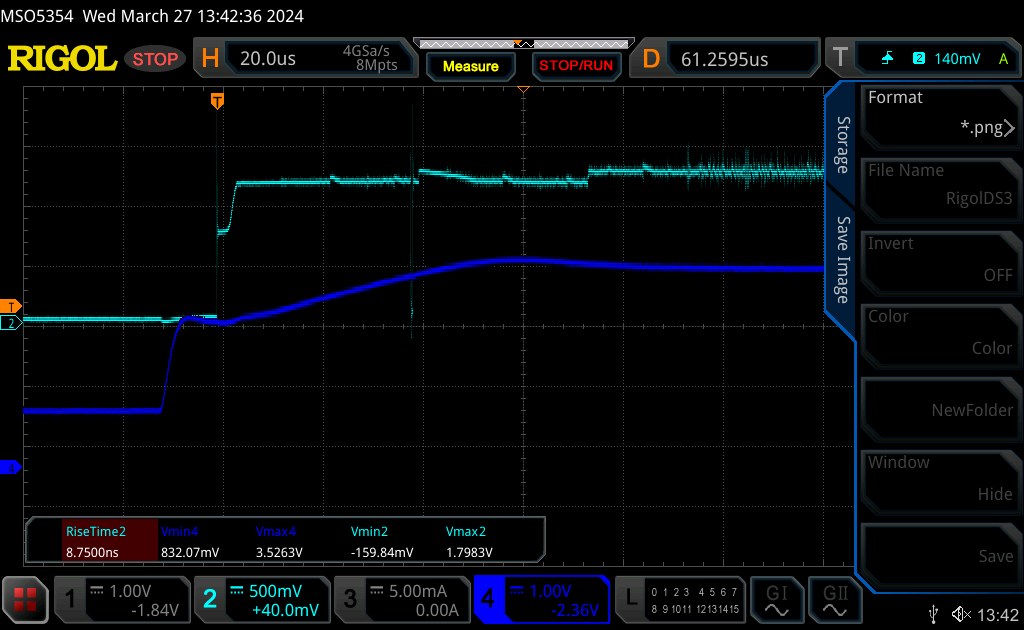
Waveform appears to be clean and I am producing 700ns glitches - see image.
I believe these are pretty good based on the tutorials, but I don’t know what I don’t know
The initial script is power cycling the target at the beginning of each test run (rather than just NRST), its slower but has seemed more consistent.
The script will glitch and then use the jlink to establish a connection, if that fails, moves onto the next glitch etc. if it connects, it dumps memory.
The script just cycles through the offset in small increments… I am not varying the width at the moment…
Given the CW team built a prototype for the ATSAM21R, which is the same core plus radio, it seems that there maybe some knowledge already out in the universe on the types of successful attacks for this MCU… Anyway if not, I appreciate the help and will keep posting on any findings… thanks in advance.
(sorry appears I am only permitted to upload 1 image at a time)
Where do you measure power supply to see the fault injection? Directly on the VCC pin or on the CW?
The wave form of fault injection will be different on opposite sides.
It is not clear whether you have enough VCC glitch to fault the IC HW.
Another suggestion… You can write the sample application with expected behaviour and try to glitch it to get the fault. At least you will find right timings and glitch duration.
Measuring on the scope which is attached to the coax cable, using a T to the CW. I have not been using a limiting resistor (eg 50 ohm) so its been a direct short o the vdd_core. When i glitch, the device is restarting, I am using a simple loop app which outputs a count on the uart from the target. Any glitch is causing a restart… so now I am thinking I need to find a better combination of limiting resistor at the CW crowbar, measure the glitch voltage on the scope at the target pin without the coax and then continue to experiment with the width.
I am not convinced that the brown out circuit on the VDD_Core isnt the problem and that a crowbar glitch isnt possible…
Have you seen any successful glitches on the ATSAMR21 ? I’ll keep trying have a lot more combinations to experiment with. Again thanks for the insights…