Bad CW Husky's output of traces

Hi.
I began discussing weird behaviour of CW Husky specific to the SCA attacks against hardware AES implementation in this thread CW Husky and CW Lite capture different traces - #13 by NewDwarf
…but feedback didn’t help me to fix the problem.
Moreover, collecting more and more traces (up to 80K) makes impossible to guess any byte of the round key even if exact leak samples are used to guess the key.
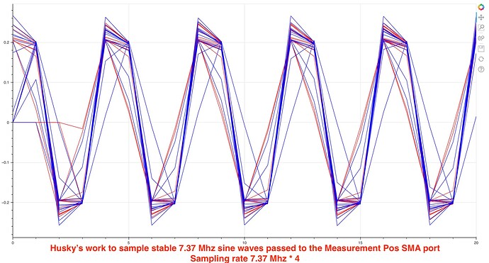
I decided to take the arbitrary signal generator, produce the 7.37 Mhz sine wave (pretty comfort conditions for any hardware) and pass it to the Husky’s “Measurement Pos” SMA port.
So, the scenario is:

  1. Husky captures the stable continuous sine wave. Capture is triggered by regular communication with the target board.
  2. Captured traces of the sine wave are synchronized by SAD for better visualization.
  3. Captured traces are visualized.

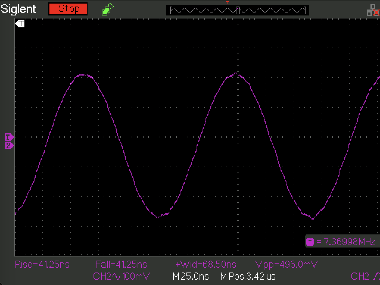
The input sine wave has 1 Vpp magnitude and it is 7.37 Mhz. The coax cable is terminated by SMA connector from one side and BNC from another side, impedance 50 Ohm.

An oscilloscope displays nice and stable sine wave.

Following script is used to capture the sine wave:

import chipwhisperer as cw                                                                                                                                                                                  
import chipwhisperer.analyzer as cwa
from bokeh.plotting import figure, show
from bokeh.io import output_notebook
from bokeh.palettes import brewer
import time
from tqdm import tqdm

scope = cw.scope()
target = cw.target(scope, cw.targets.SimpleSerial2)

time.sleep(0.05)
scope.default_setup()

time.sleep(0.05)
scope.io.nrst = 'low'
time.sleep(0.05)
scope.io.nrst = 'high_z'

scope.gain.db = 10

scope.adc.samples = 1148
scope.adc.offset = 0
scope.adc.basic_mode = "rising_edge"

scope.clock.adc_mul = 4

scope.clock.reset_adc()
assert (scope.clock.adc_locked), "ADC failed to lock"

project = cw.create_project("traces/tmp_hw_aes.cwp", overwrite=True)

ktp = cw.ktp.Basic()
N = 200


for i in tqdm(range(N)):
    key, text = ktp.next()
    trace = cw.capture_trace(scope, target, text, key)
    if trace is None:
        continue
    project.traces.append(trace)

print(scope.adc.trig_count)

scope.dis()
target.dis()


resync_traces = cwa.preprocessing.ResyncSAD(project)
resync_traces.ref_trace = 0
resync_traces.target_window = (3, 7)
resync_traces.max_shift = 3
resync_analyzer = resync_traces.preprocess()

p = figure(sizing_mode='scale_width', plot_height=300, x_range=(0, 20))

xrange = range(0, len(resync_analyzer.waves[0]))

for i in range(0, 15):
    p.line(xrange, resync_analyzer.waves[i], line_color="red")

for i in range(50, 15):
    p.line(xrange, resync_analyzer.waves[i], line_color="green")

for i in range(100, 115):
    p.line(xrange, resync_analyzer.waves[i], line_color="blue")

show(p)

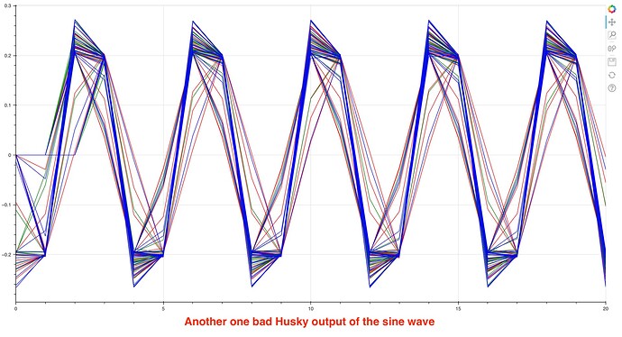
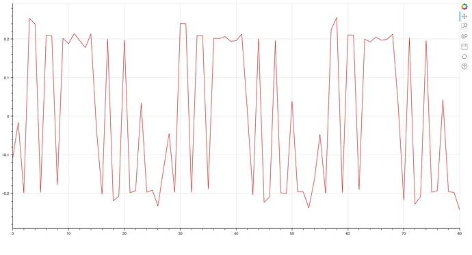
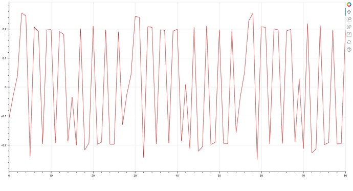
The script gives such output:

I am not a digital signal processing expert but I would expect to see single blue line with tiny jitter.
Produced by Husky’s ADC output has different amplitude, very high jitter and kind of phase shifting.
The output definitely doesn’t look perfect.

And ultimately, an explanation of why great number of collected power traces brings a lot of noise so that any byte of the round key cannot be guessed.

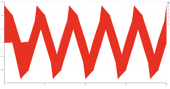
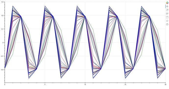
Below is visualization of 20000 traces of the stable syne wave 7.37 Mhz

Here, I would expect to see thin red line instead of this noisy picture.
Aligned in-place sine wave traces

for CW Husky

and, in contrast, for CW Lite

CW lite digitizes much much better than CW Husky. Due to small issue with fall time of the wave being generated we can see two “fall lines” for CW Lite. But “rise line” is perfect.

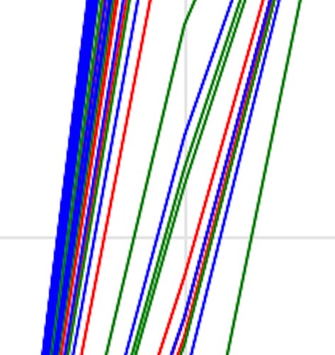
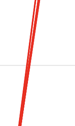
Also, take a look at the zoomed in pictures

For CW Husky:

For CW Lite:

The question is how to deal with the Husky issue? It (at least my sample) is totally unusable for the HW SCA attacks.
What might be the reason of this issue? Bad parameters of the ADC, FPGA or something wrong with the FPGA code?

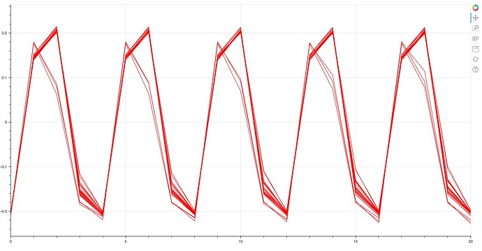
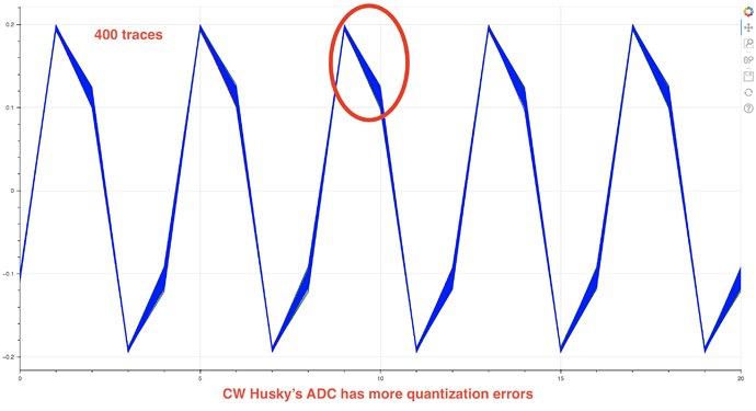
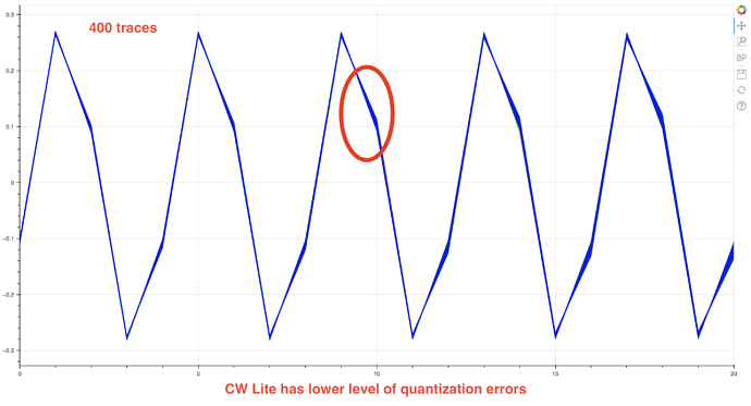
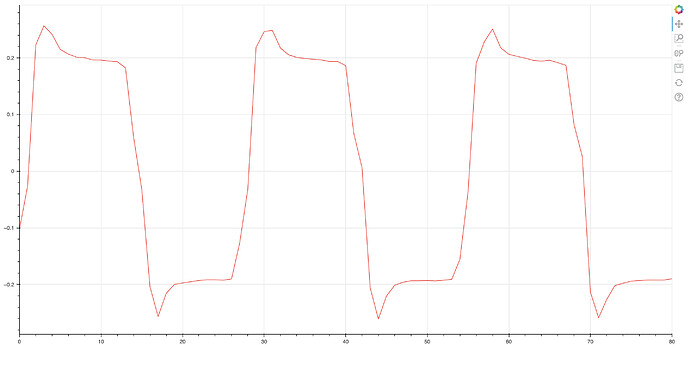
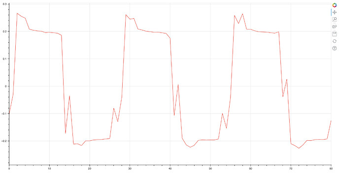
After improving jitter of the sine wave source and decreasing AC-coupling sine wave from 1 V to 200 mV I get following pictures

For Husky:

For Lite:

I have suspicious this is quantization issue with the CW Husky.
@jpthibault What is the principal difference in quantization between Husky and Lite?

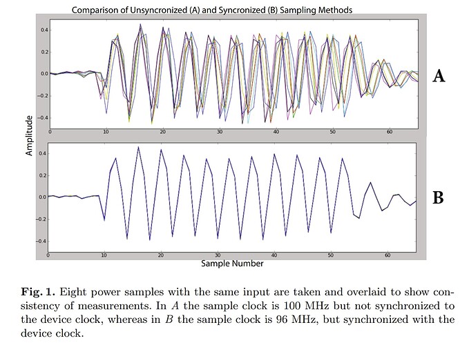
One other note here - what you are seeing is I think the problem with the asynchronous vs. synchronous capture on the external input. This is an old photo but shows the difference:

You may want to increase the sample frequency if measuring an external asynchronous clock. The normal x4 is roughly based on generating normal-looking synchronous traces. Something like this will capture at higher frequencies:

scope.clock.adc_mul = 1
scope.clock.clkgen_freq = 200E6

Also as you found the lower input voltages will be better - as the frontend is mostly amplifier, it’s easy to overload it at 1V input or similar! You could see if lower results (or playing with gain setting) gives you better results.

It should give you a clean-looking sine wave if you increase the sample rate, which should help understand exactly what’s going on there.

Hi @coflynn
Thanks for your answer. I tried to increase ADC frequency up to 200 Mhz. The results confused me even more :crazy_face:
Exactly the same script captures and digitize the sine wave (7.37 Mhz) very differently.
Here are the samples I got:
possibly normal shot:

close to normal:

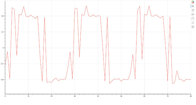
distorted trace:

more distorted:

very distorted:

The sine wave captured by the oscilloscope looks:

It is definitely something wrong with, at least, my CW Husky sample.

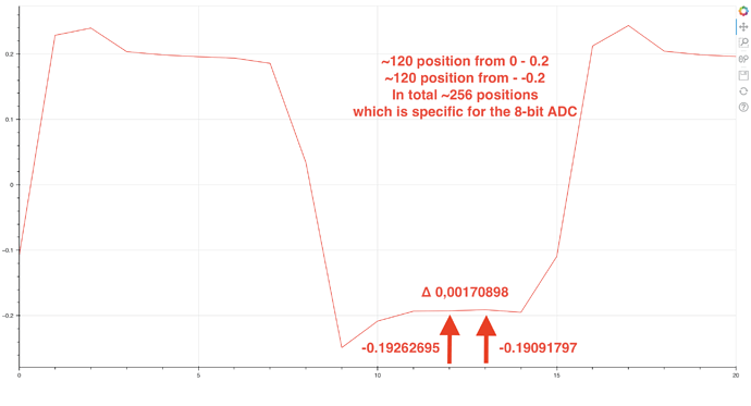
@coflynn Also, I tried to calculate ADC resolution using the square wave as I found it more suitable to get the minimal difference between two consecutive samples.
And I got ~256 states which is actually 8-bit resolution.

The numpy array for this trace is

[-0.10766602  0.22875977  0.23974609  0.20361328  0.19873047  0.19604492
  0.19384766  0.18579102  0.03393555 -0.2487793  -0.20825195 -0.19311523
 -0.19262695 -0.19091797 -0.19482422 -0.109375    0.21240234  0.24365234
  0.2043457   0.19897461  0.19628906  0.19384766  0.18652344  0.03222656
  ...
]

That’s easily disproven. The problem with your example is that (1) you’re not working over the full [-0.5, +0.5] range, and (2) you’ve picked two samples that look close together but that does not prove that you’ve landed on the minimum step.

Here I’ll use the as_int=True option to obtain trace samples as integers in the range [0, 2^12-1]. Without this option, the trace samples are mapped to floats in the range [-0.5, +0.5]; you can do that as well, it’s just easier to show with integers:

import chipwhisperer as cw
PLATFORM = 'CWLITEARM'
%run ../Setup_Scripts/Setup_Generic.ipynb
scope.default_setup()
trace = cw.capture_trace(scope, target, bytearray(16), bytearray(16), as_int=True)
min(trace.wave), max(trace.wave)

returns: (779, 2696)

import numpy as np
sorted_trace = np.sort(trace.wave)
sorted_trace[:10]

returns: array([ 779, 1278, 1414, 1428, 1428, 1432, 1441, 1442, 1442, 1445], dtype=uint16)

With regards to your distorted plots: as Colin pointed out, CW isn’t a general-purpose oscilloscope, its analog front-end is designed for very small signals.

@jpthibault What are the high and low limits in your power trace? Without the range, it is impossible to bind the values of the points, you got, to the highest and lowest points of the trace to calculate the real resolution.
How the float points are mapped to the int points?

It’s really straightforward: [0, 4095] is mapped linearly to floats in the range [-0.5, +0.5].

@jpthibault Thanks.
Yes. I can confirm that Husky’s output is 12-bit output according to obtained data.
The snipped of the captured samples with delta equal to 1 which confirms 12-bit ADC.

...
2139 2140 2141 2142 2143 2144 2145 2146 2147 2148 2149 2150 2151 2152
...

Although, it worths to mention that the Effective number of bits (ENOB) value is 11.2 bits according to ADC’s spec.
But it is still not so important…
The fun facts are:

  1. Increasing the number of the samples being collected (up to 60-80K) makes impossible to guess any byte of the key. Should be opposite in theory. All traces are well syncronized.
  2. Choosing the value scope.clock.adc_mul in the range 4-27 has almost the same effect.
  3. Choosing the value scope.clock.adc_phase from 0 to 255 with the step 30 has the same effect from 0 to 90. 90+ makes impossible to guess any key byte.
  4. Playing with the scope.gain.db value to fit in the range [-0.45 … 0.45] helps to guess the same 3-4 bytes of the round key. Decreasing scope.gain.db value squeezes the power traces in the range [-0.2 … 0.2] and the key bytes cannot be guessed.

I will bet the new unexperienced user just throw Husky if it gives the same experience I have with it.
But hopefully, I have the CW Lite and learnt with it to something so that I can do a little analyzis and evaluate correct/uncorrect results.

NewAE guys, I believe you have the CW Husky and the STM32F4 HW AES based target board.
I would kindly ask you to try to recover the AES key using Husky. If it really works, it will take 5-10 min of your time.

Addressed here.