On capturing the power traces, I noticed that the ADC and Glitch LED’s are periodically blinks together.
The blinking interval is 1-2 sec.
At the same time, the traces are captured correctly (at least from the python logic perspective).
It is difficult to understand what is the reason of this blinking.
I additionally uncommented logging of adjusting of ADC.
The tails of the log is:
New best: in_div 1 out_div 21 pll_mull 40 prescale 4 error 0.19047619047619047 freq 28571428.57142857
New best: in_div 1 out_div 21 pll_mull 41 prescale 5 error 0.023809523809523787 freq 23428571.42857143
New best: in_div 1 out_div 21 pll_mull 42 prescale 5 error 0.0 freq 24000000.0
100%|██████████████████████████████████████████████████████████████████████████████████████████████████████████████████████████████████████████████████████████████████| 2000/2000 [00:16<00:00, 123.01it/s]
663
The python script
import chipwhisperer as cw
import time
from tqdm import tqdm

scope = cw.scope()
target = cw.target(scope, cw.targets.SimpleSerial2)
target.baud = 115200

scope.default_setup()

scope.gain.db = 38

scope.adc.samples = 2000
scope.adc.offset = 0
scope.adc.basic_mode = "rising_edge"

scope.clock.clkgen_freq = 24000000
scope.clock.adc_mul = 7

scope.trigger.triggers='tio3'

project = cw.create_project("traces/HW_AES.cwp", overwrite=True)

ktp = cw.ktp.Basic()
N = 2000

for i in tqdm(range(N)):
    key, text = ktp.next()
    trace = cw.capture_trace(scope, target, text, key)
    if trace is None:
        continue
    project.traces.append(trace)

print(scope.adc.trig_count)
project.save()

scope.dis()
target.dis()
What can be a reason of this blinking? How to debug the problem?
It means Husky detected an error condition, check scope.errors to learn what it is.
Explained here, section 1.
Forgot to mention, the blinking stops when script stops working.
I get the scope.error output. Looks like there are no errors.
sam_errors = False
sam_led_setting = Default
XADC errors = False
ADC errors = False
extclk error = False
trace errors = False
After several attempts I got the error message
sam_errors = False
sam_led_setting = Default
XADC errors = False
ADC errors = slow FIFO underflow, trigger too soon error,
extclk error = False
trace errors = False
@jpthibault Maybe this is because of too fast HW AES on my target platform?
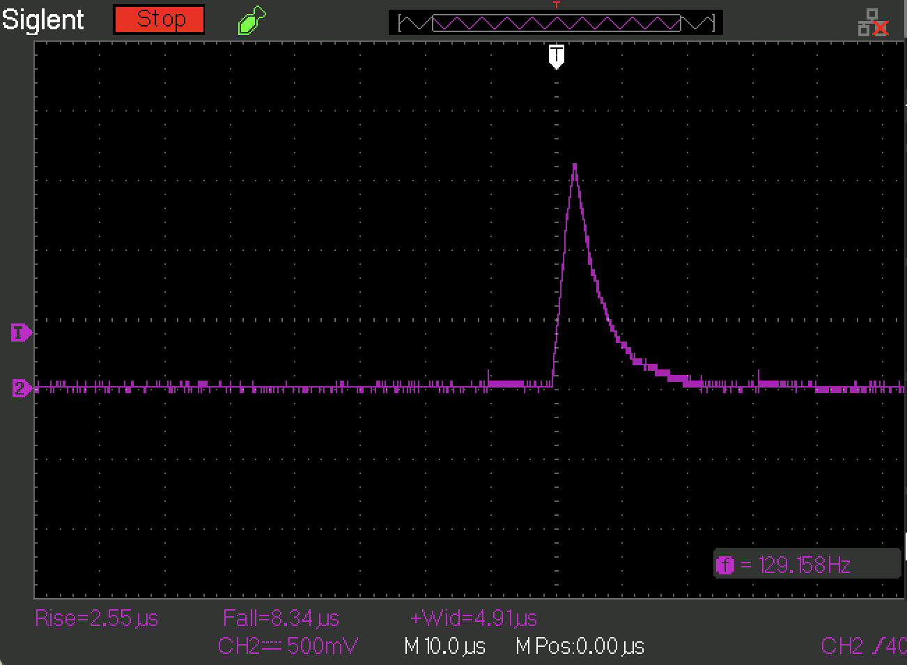
Below is the trigger trace. As trigger_high() and trigger_low() happen very close to each other, the trigger level goes only up to 1.5V. Width of the spike is ~5us. I am not sure whether FPGA is able to process these changes.
@jpthibault I have added 1ms delay to guarantee trigger detection. But it doesn’t fix appearing the
ADC errors = slow FIFO underflow, trigger too soon error
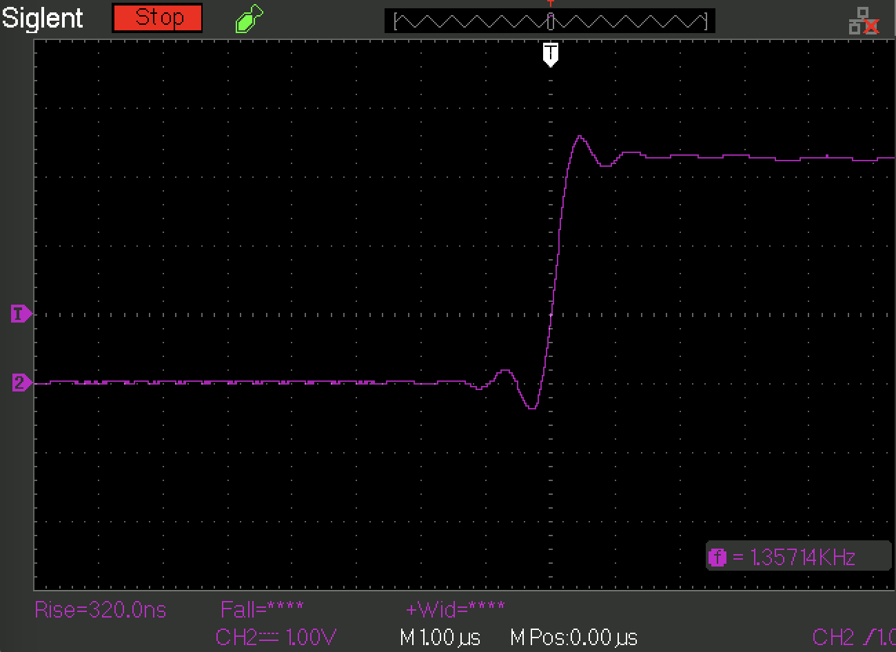
Below if the trigger trace for 1ms when error still happens
…and the runtime clock parameters
clock =
clkgen_src = system
clkgen_freq = 24000000.0
adc_mul = 7
adc_freq = 168000000.0. // 168 MHz
freq_ctr = 0
freq_ctr_src = extclk
clkgen_locked = True
adc_phase = 0
extclk_monitor_enabled = False
extclk_error = False
extclk_tolerance = 13096723.705530167
One more question. Should the coax cable mandatory be connected to the measurement port on the CW Husky?
The measurement part is not ready on the target port yet and I just implemented communication between the CW Husky and the target board.
The trigger line is sampled using the ADC clock. 5us is WAY more than enough. But the fact that it only goes to 1.5V can be problematic. That is a very slow rise. But given that your target isn’t able to overcome the FPGA’s pull-down on TIO4, not so surprising.
I would clear the scope errors and focus on seeing if you can run a single clean capture, without any errors.
There is no need for the measurement port to be connected.
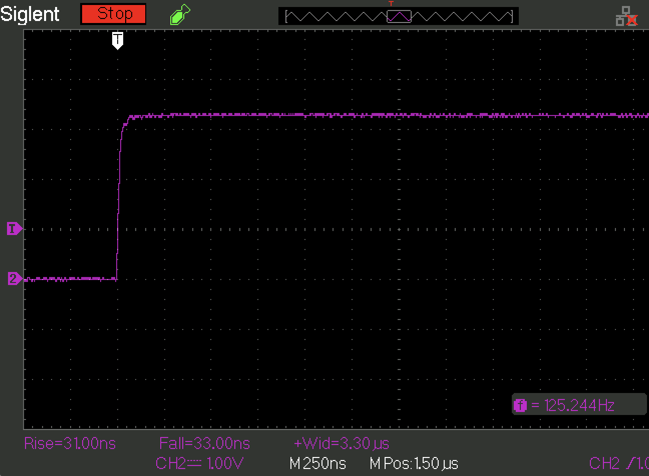
@jpthibault I improved GPIO output. Now I have 320 ns rise time and able to drive the TIO4 port.
Runtime (real triggering of the TIO4 by the GPIO line) trace looks perfect.
All errors were gone.
What did you do to improve the GPIO output? I am having a similar issue
There was a problem with programmatic GPIO configuration.
What SoC you are trying to use?
I’m using a Husky with the Artix A35 target
What is rise time in your case and what is rise time of I/O in the A35 spec?
Looks like, the perfect rise time value is 5ns/V. But in my case, 30-40ns was also fine.
I don’t have access to the equipment right now that would tell me the rise time, but thanks for the info with the 5ns/V. What values did you change programmatically to affect the rise time?
The SoC I worked has pretty complex I/O configuration. Originally, I decided to just pull up/pull down the port globally. But it gave bad results(slow rise time).
Then I applied more complex approach - enabled globally I/O and drive output by means of playing with the control registers responsible for driving the output signal.
BTW, are you trying to run the side channel attack?
Originally, I decided to just pull up/pull down the port globally.
That’s what I’m currently doing (it was the only way that I wouldn’t get a trigger timeout error), but I think that it could be contributing to the cause of my issue (I’m getting an ADC “trigger too soon error” like you were).
I may have to mess around with the registers as well; I haven’t been able to find any programmatic solutions that involve adjusting the scope settings and inserting small delays between various instructions that seem like they may cause issues if not allowed to run to completion before the next operation is called.
BTW, are you trying to run the side channel attack?
Yeah, I am
There was a bug were the scope.adc.errors reporting swapped the “trigger too soon” and “gain too low” errors (fixed here). Sorry for the confusion this appears to have caused.
If you’re using our A35 target, then you really shouldn’t need to worry about trigger rise times. Just make sure you set the I/Os to 3.3V in your Vivado constraints file (as we do in our examples).