Okay we’ve done a lot of work trying to set up voltage glitching on a target of our own, a MAX78000FTHR board. We removed all the decoupling capacitors (and a buck converter) attached to VCOREA with the exception of a tiny one, C9. We cut an SMA cable so the crowbar is soldered to a Dupont jumper cable connected to PCbite which is touching the positive end of the tiny C9 capacitor. We wrote our own firmware that goes on the device that waits 1ms then runs in a loop 50,000 times and adds 1 to the sum each time in the loop (basic “can you make it not be 50000” setup). We wrote our own custom Target class that interfaces with this loop correctly and have verified that it works.
So now, the next move seemed to be trying to get a glitch happening on the board then we can work more on fine tuning parameters like width, offset, and ext_offset. However with glitch_hp=True, we never get any glitches, even with the max width. Also with glitch_lp=True, the first run causes a hard glitch that resets the board, then normal from there.
Note that the MAX78000 CPU runs at 100MHz which I know is kind of high but I think we made all the settings correct? I’ve attached some snippets below of our code that describes the setup and what we’re doing.
import chipwhisperer as cw

scope = cw.scope(scope_type=cw.scopes.OpenADC)
scope.adc.samples = 131070                          # max supported number by the Husky
scope.gain.gain = 22                                # default setting
scope.clock.adc_mul = 2
scope.clock.clkgen_freq = 100_000_000 # 100MHz, speed of MAX78000 CPU

target = eCTF2025Target('/dev/ttyACM1', 115200, 0.5)

def reset_target():
    """
    CW's nRST pin is connected to MAX78000's RST pin. Bringing it low then high
    will power cycle the board. Total time = 0.55s
    """

    global scope
    sleep(0.05)
    scope.io.nrst = 'low'
    sleep(0.05)
    scope.io.nrst = 'high_z'
    sleep(0.45) # this is as little as I can wait for it to finish starting up

reset_target()

# set up the LED glitch trigger condition
scope.trigger.module = "edge_counter"
scope.trigger.edges = 1
scope.trigger.triggers = 'tio1'


# set up the glitch controller
gc = cw.GlitchController(groups=["success", "reset", "normal"], parameters=["width", "offset", "ext_offset", "tries"])
scope.glitch.enabled = True
scope.glitch.clk_src = "pll"                        # our internal PLL is generating the 100MHz clock freq, not an external source
scope.io.glitch_hp = True
scope.io.glitch_lp = False

scope.glitch.output = "glitch_only"                 # don't do anything with the clock
scope.glitch.trigger_src = "ext_single"             # our trigger condition is set above

scope.adc.timeout = 0.01                            # it takes between 0.002 and 0.005 seconds for the loop to run

### SET PARAMETERS ###
"""
Note that no matter what these settings are, with glitch_hp we NEVER see any glitches on our logic analyzer, and with glitch_lp only the FIRST one hard glitches (even if we set width to 0).

Since our clock freq is 100MHz, phase_shift_steps is set to 336.
"""

# generic setting, if we don't do this we can't set steps below
gc.set_global_step(10)

# how many times will we do it with each setting?
gc.set_range("tries", 0, 3)
gc.set_step("tries", 1)

# How wide should the glitch be (in terms of phase shift steps) from 0 to 168?
gc.set_range("width", 0, 168)
gc.set_step("width", 40)

# How far along inSIDE of the clock cycle should be glitch be delivered (in terms of phase
# shift steps) from 0 to 336?
# Note - we probably want to start at 168 as this is where the falling clock edge starts
gc.set_range("offset", 0, 336)
gc.set_step("offset", 40)

# How many clock cycles after the trigger should we be sending our glitch?
gc.set_range("ext_offset", 30, 50)
gc.set_step("ext_offset", 10)

resets = 0
successes = 0

for glitch_setting in gc.glitch_values():
    # gc.glitch_values() iterates through all our settings and returns a tuple of them
    width   = glitch_setting[0]
    offset  = glitch_setting[1]
    ext_off = glitch_setting[2]
    try_no  = glitch_setting[3]

    print(f"[+] width: {width}, offset: {offset}, ext_offset: {ext_off}, try_no: {try_no}")

    if scope.adc.state:
        # can detect crash here (fast) before timing out (slow)
        reset_target()
        gc.add("reset")
        resets += 1
        print("[-] Reset from adc.state")

    # NOW everything is set up for the glitch, let's start it
    print("[+] Sending glitch")
    scope.arm()
    good, sum_val = target.get_loop()
    scope.io.vglitch_reset()

    if not good and sum_val == 1:
        reset_target()
        gc.add("reset")
        resets += 1
        print(f"[-] UART response timed out")
    elif not good and sum_val == 0:
        reset_target()
        gc.add("reset")
        resets += 1
        print(f"[-] Bad UART response data")
    elif sum_val == 50000:
        gc.add("normal")
        print("[+] Normal")
    else:
        gc.add("success")
        successes += 1
        print("[+] Success!")

    scope.sc.arm(False)
Note that we also have a Saleae Logic Analyzer connected to the probes so we can see everything that’s happening (ik the husky also has capabilities like this but we’re more familiar with it). We’ve simply clipped the logic analyzer wires to the PCbite ends.
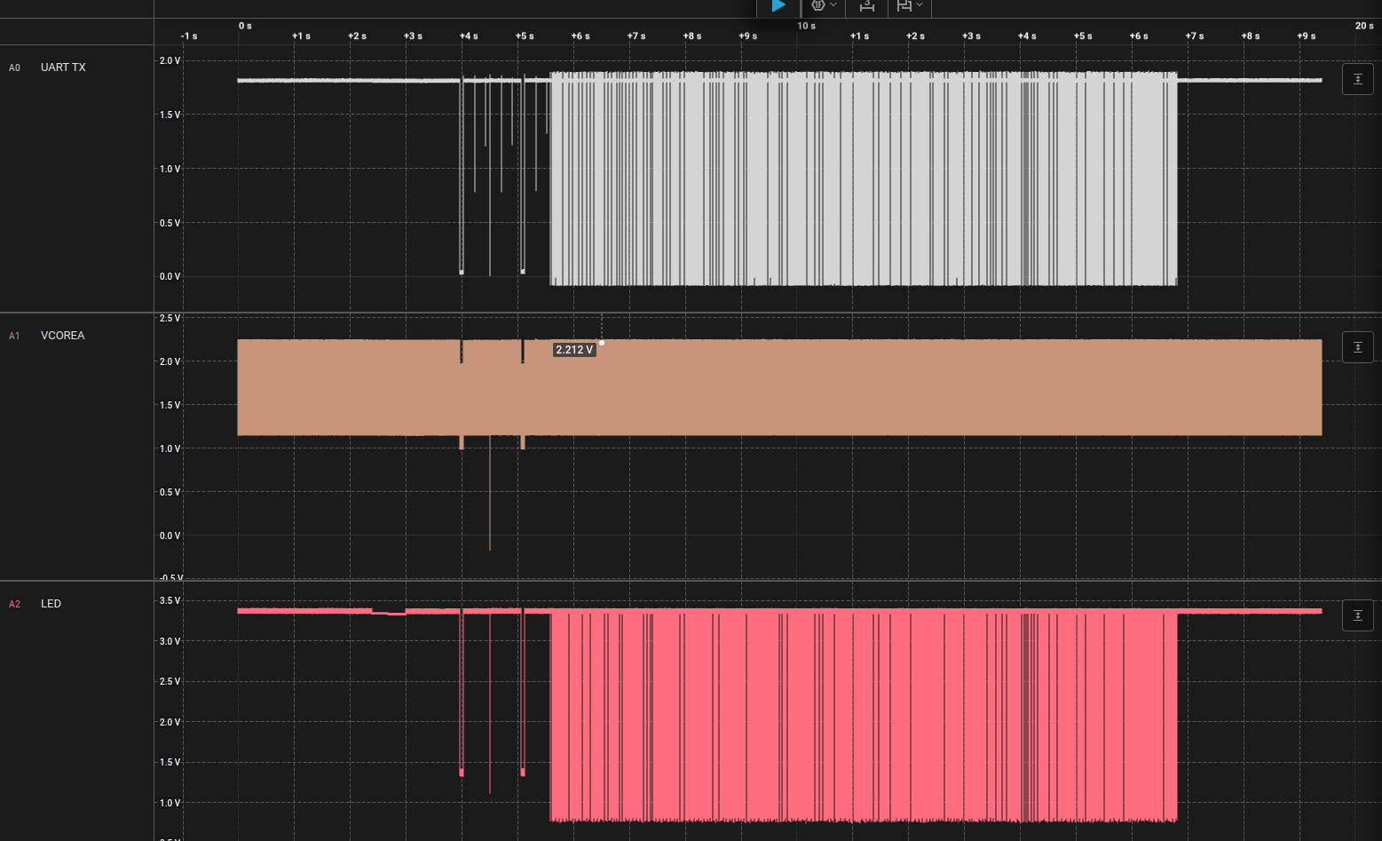
Here’s an example of running it with glitch_lp = True. The first little spike on VCOREA around 4s is our first reset. The big spike after that is when it glitched the thing and had to be reset (next little spike around 5s). No more spikes after that.
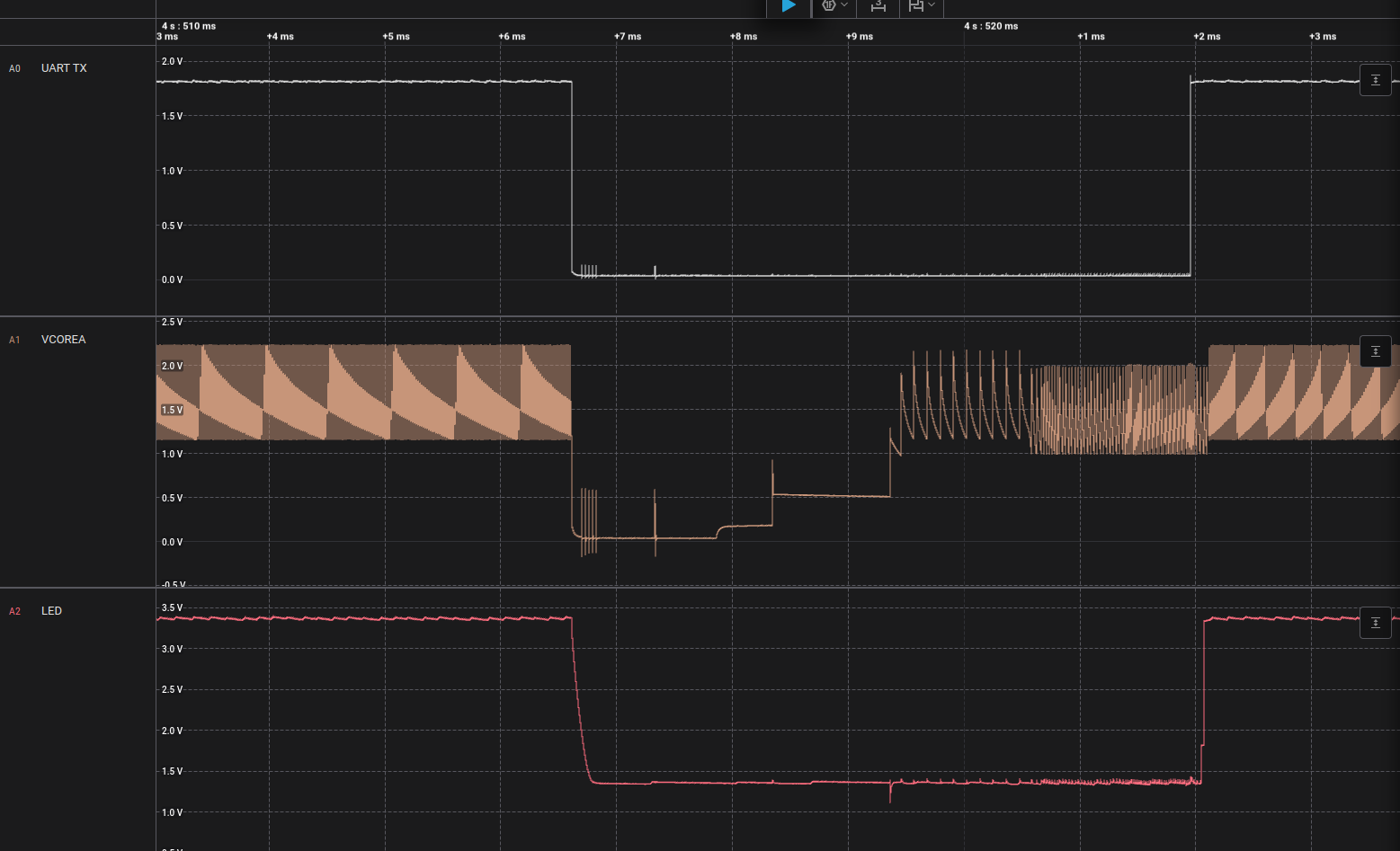
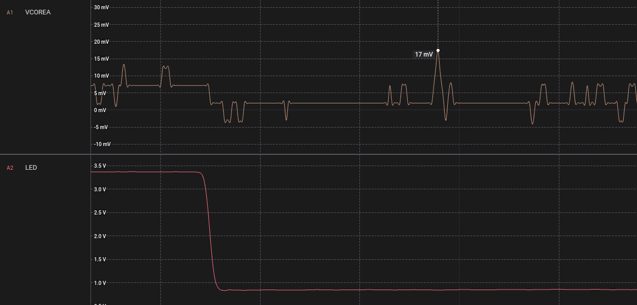
Here’s a close up of the glitch happening. The thing that I don’t understand is the MOMENT we set glitch_lp = True, once we send UART data this happens. Even if we don’t arm the scope, even if we haven’t set glitch parameters yet. If we literally do
# set up target

scope.io.glitch_lp = True

target.get_loop()
It will do that spike the first time. We haven’t armed it or set any parameters but it still goes, and then that never happens again. We are sure the board is working past that point because we still get the 50,000 sum response from the loop messages. Our trigger is found, the loop seems to be working, and the logic analyzer shows all the data so we think it’s all connected properly.
Any idea what we’re doing wrong? I can send a picture of our setup or more code if you need.