So just to recap I’ve ran two version of the code with a scope.glitch.repeat = 1 and scope.glitch.repeat = 4. For each run I’ve captured the MCX port and then the Pos LP measurement port. I’ve also included the code and output below of a scope.glitch.repeat = 4. Let me know if there is anything else I can test/try to confirm what could be wrong…
scope.glitch.repeat = 1
Yellow = MCX Port
Purple = The blinking led
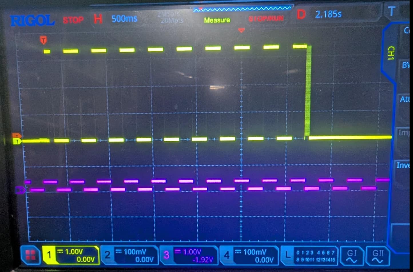
scope.glitch.repeat = 1
Yellow = Pos LP port
Purple = The blinking led
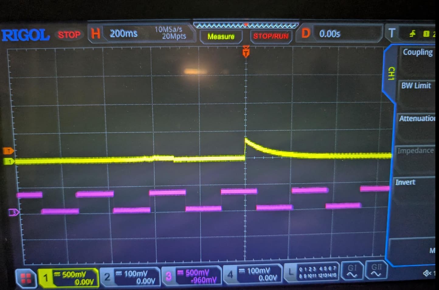
scope.glitch.repeat = 4
Yellow = MCX Port
Purple = The blinking led
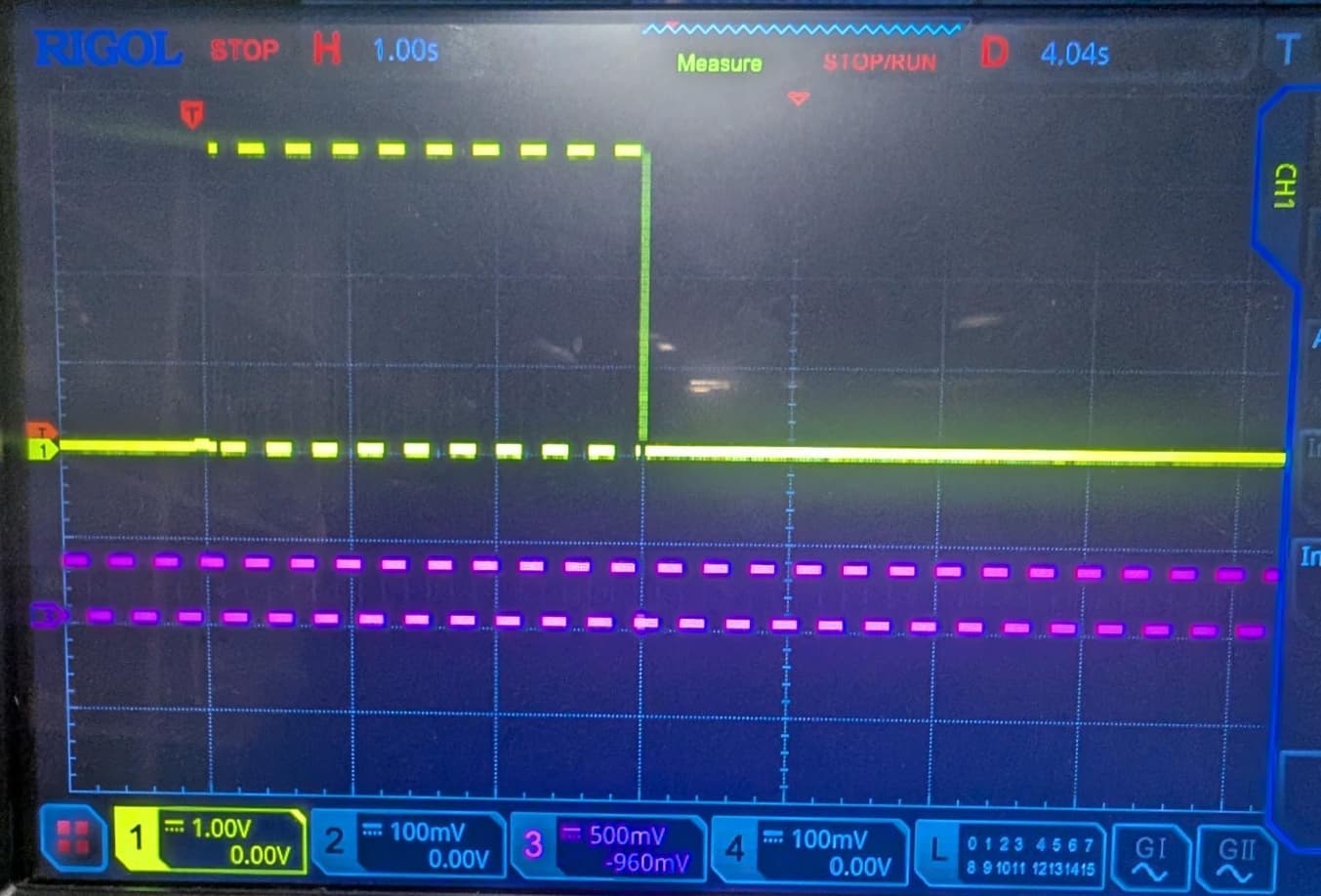
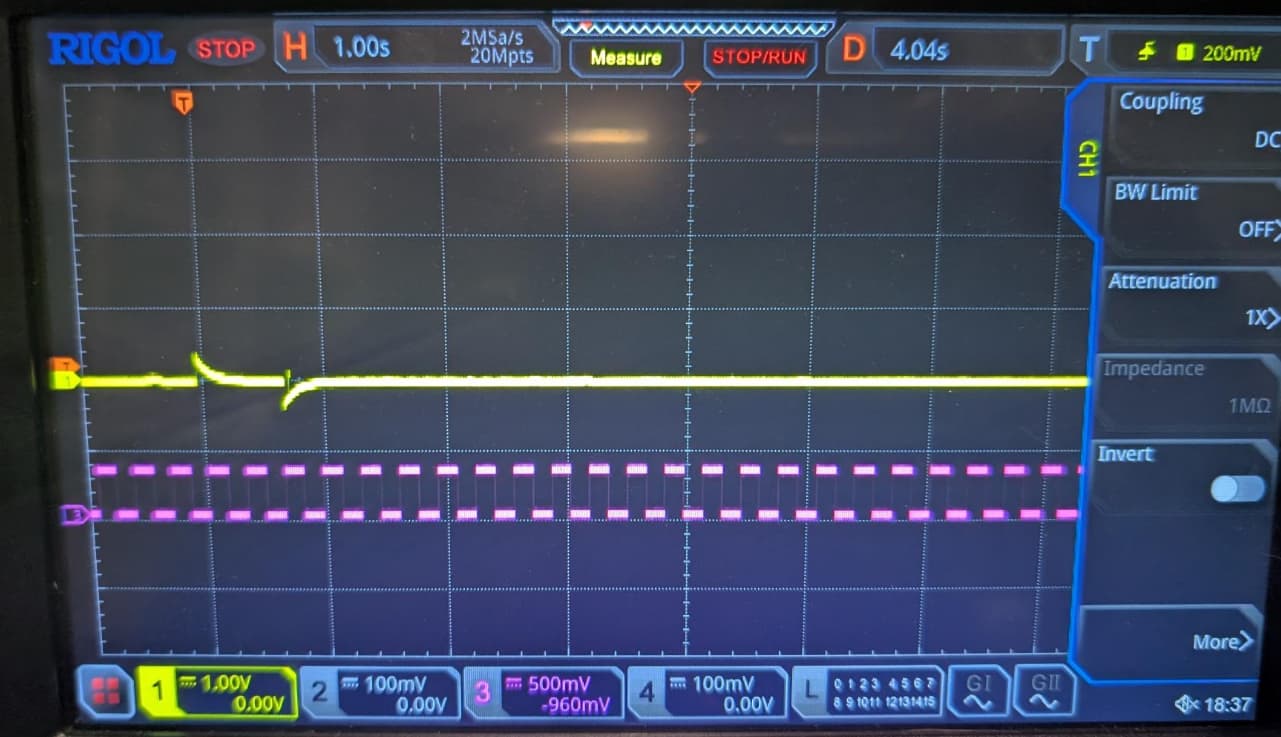
scope.glitch.repeat = 4
Yellow = Pos LP port
Purple = The blinking led
import chipwhisperer as cw

from chipwhisperer.common.results.glitch import GlitchController

from glitcher import Glitcher
from chipshouter import ChipSHOUTER
import time
import logging
import sys

port = "/dev/ttyUSB0"

def main():

    scope = cw.scope(name='Husky')
    scope.adc.lo_gain_errors_disabled = True
    print(scope.fw_version)
    print(scope.fw_version_str)

    # Setup the clock to use and what speed to run it at
    scope.clock.clkgen_src = 'system'       # "system" or "internal": An onboard crystal
    scope.clock.clkgen_freq = 40e6          # This is used for the glitching clock i.e. the higher the more accurate the
                                            # glitch occurs from the trigger The maximum is 200MHz (Husky)
    scope.clock.adc_mul = 1                 # Sets a new ADC clock frequency by multiplying this value by clkgen_freq
                                            # setting to 1 just leaves the clk freq at scope.clock.clkgen_freq
    scope.adc_test()
    # Setup what and how we are going to be triggered
    scope.trigger.triggers = 'tio4'         # This is the I/O pin 4 we will be getting the trigger signal from
    scope.trigger.module = 'edge_counter'   # Choose how to trigger, in this case its based on the number of edges
                                            # we see i.e. like a clock
    scope.trigger.edges = 1
    scope.adc.timeout = 2

    # Setup the chipshouter to glitch
    scope.io.glitch_trig_mcx = "glitch"     # Setup the MCX on the husky to output for a glitch
    scope.glitch.enabled = True             # This enables the glitch module
    scope.glitch.clk_src = 'pll'            # This is the clock source on the husky, so the offset and widths relate to this clock
    scope.clock.pll.update_fpga_vco(600e6)

    scope.glitch.trigger_src = "ext_single" # XXX ext_single in real use case
    scope.glitch.output = "enable_only"
    scope.io.glitch_lp = True

    scope.glitch.arm_timing = "after_scope"

    scope.glitch.repeat = 4               # The number of glitch pulses to generate per trigger
    scope.glitch.ext_offset = [0,0]       # Only works with enable_only after the glitch module is triggered, it waits for a number of clock cycles before generating glitch pulses. This delay allows the glitch to be inserted at a precise moment during the target’s execution to glitch specific instructions.
    print(f"Offset: {scope.glitch.ext_offset}")
    #scope.glitch.offset = 500            # only works with glitch_only
    #scope.glitch.width = 500             # only works when glitch_only
    print(f"Phase shift steps: {scope.glitch.phase_shift_steps}")
    print(f"The glitch repeats: {scope.glitch.repeat}")
    assert scope.glitch.mmcm_locked         # ???

    print("Scope Glitch:")
    print(scope.glitch)
    print("Scope Trigger:")
    print(scope.trigger)
    print("Scope IO:")
    print(scope.io)
    print("Scope Clock:")
    print(scope.clock)

    scope.sc.arm(False)
    scope.arm()
    print("ARM Scope and glitcher")


    print(f"Start Capture timeout (sec): {scope.adc.timeout }")
    if(scope.capture()):                        # Blocks until scope.adc.timeout reached or matching signal found at scope.trigger.triggers
        print("Timeout occurred no edges seen")
    else:
        print(f"Edges seen: {scope.trigger.edges_seen}")

    print(f"XADC errors: {scope.XADC.status}")
    print(f"ADC errors: {scope.adc.errors}")
    print(f"Extclk errors:{scope.clock.extclk_error}")

    scope.dis()                             # Disconnect from the Husky

    exit()

if __name__ == "__main__":
    main()
python source/chip_whisperer_husky_forum.py
{'major': 1, 'minor': 5, 'debug': 0}
1.5.0
Offset: 0
Phase shift steps: 840
The glitch repeats: 4
Scope Glitch:
enabled           = True
num_glitches      = 1
clk_src           = pll
mmcm_locked       = True
width             = 0
offset            = 0
trigger_src       = ext_single
arm_timing        = after_scope
ext_offset        = 0
repeat            = 4
output            = enable_only
phase_shift_steps = 840

Scope Trigger:
sequencer_enabled = False
module            = edge_counter
triggers          = tio4
edges             = 1

Scope IO:
tio1            = serial_tx
tio2            = serial_rx
tio3            = high_z
tio4            = high_z
pdid            = high_z
pdic            = high_z
nrst            = high_z
glitch_hp       = False
glitch_lp       = True
extclk_src      = hs1
hs2             = None
target_pwr      = True
tio_states      = (1, 1, 1, 1)
cdc_settings    = bytearray(b'\x01\x00\x00\x00')
aux_io_mcx      = high_z
glitch_trig_mcx = glitch

Scope Clock:
clkgen_src             = system
clkgen_freq            = 40000000.0
adc_mul                = 1
adc_freq               = 40000000.0
freq_ctr               = 0
freq_ctr_src           = extclk
clkgen_locked          = True
adc_phase              = 0.0
extclk_monitor_enabled = False
extclk_error           = False
extclk_tolerance       = 1144409.1796875

ARM Scope and glitcher
Start Capture timeout (sec): 2
Edges seen: 1
XADC errors: good
ADC errors: gain too low error,
Extclk errors:False