Hopefully a easy one, I’m just trying to create a basic test with the “simple trigger” target board.
I’ve got tio4 connected on the husky to the “run” led on the target board to act as trigger. I’m
trying to then count 2 edges (i.e. blinks of the led) and then send a glitch to the chipshouter.
What I’m seeing is the husky sends a glitch almost immediately after “scope.arm()” and reporting that it has seen 0 edges, so I don’t understand how it or what it causing it to trigger.
This is the following code I’m using:
    scope = cw.scope(name='Husky')

    # Setup the clock to use and what speed to run it at
    scope.clock.clkgen_src = 'system'       # "system" or "internal": An onboard crystal
    scope.clock.clkgen_freq = 20e6          # This is used for the glitching clock i.e. the higher the more accurate the
                                            # glitch occurs from the trigger The maximum is 200MHz (Husky)
    scope.clock.adc_mul = 1                 # Sets a new ADC clock frequency by multiplying this value by clkgen_freq
                                            # setting to 1 just leaves the clk freq at scope.clock.clkgen_freq
    scope.adc.trig_count
    # Setup what and how we are going to be triggered
    scope.trigger.triggers = 'tio4'         # This is the I/O pin 1 we will be getting the trigger signal from
    scope.trigger.module = 'edge_counter'   # Choose how to trigger, in this case its based on the number of edges
                                            # we see i.e. like a clock
    scope.trigger.edges = 2


    logging.debug(scope.trigger)            # Display the trigger settings

    # Setup and enable the glitch output
    scope.io.glitch_trig_mcx = "glitch"     # This is what the MCX connector on the Husky should be used for
                                            # we want to send a glitch pulse to the chipshouter so we use glitch
    scope.glitch.enabled = True             # This enables the glitch module
    scope.glitch.clk_src = 'pll'            # This is the clock source on the husky, so the offset and widths relate to this clock
    #scope.clock.pll.update_fpga_vco(600e6)  # ???

    # Choice of how the output glitch is formed
    # by the clock or by the trigger
    #scope.glitch.output = 'glitch_only'    # This is sync'd with the clk_src and can change the width (how long to pulse) and offset (time after the trigger)
    scope.glitch.output = 'enable_only'    # This doesn't enable control of the glitch width it just a offset from
                                            # the trigger and a number of repeats

    # This is what will happen once the scope is triggered
    scope.glitch.trigger_src = 'ext_single' # Once the scope is armed, one set of glitch events is emitted when the
                                            # trigger condition is satisfied. Subsequent trigger conditions are ignored
                                            # unless the scope is re-armed
                                            # ext_continuous ext_single

    scope.glitch.arm_timing = 'after_scope' # “after_scope”: The scope is armed first. This is the default

    # Works with enable_only
    # As we are doing a external trigger using the husky it
    # controls the pulse width of the chipshouter
    scope.glitch.repeat = 1                # The number of glitch pulses to generate per trigger
    scope.glitch.ext_offset = 0             # Only works with enable_only after the glitch module is triggered, it waits for a number of clock cycles before generating glitch pulses. This delay allows the glitch to be inserted at a precise moment during the target’s execution to glitch specific instructions.


    assert scope.glitch.mmcm_locked         # ???


    logging.debug(f"offset {scope.glitch.offset}, width {scope.glitch.width}, repeat {scope.glitch.repeat}")


    shouter = ChipSHOUTER(port)
    shouter.armed = False
    logging.debug(f"{shouter.state}")
    shouter.faults_current = 0
    logging.debug("ARM Scope first time")

    scope.arm()                             # Once armed a glitch can occur
    shouter.armed = True
    logging.debug(f"Edges seen: {scope.trigger.edges_seen}")
    scope.dis()                             # Disconnect from the Husky

    exit()
Setting aside the ChipShouter for now, your Husky code looks ok, except that when calling scope.arm() directly like this, it needs to get explicitly disarmed before it can get armed again, with scope.sc.arm(False).
I recommend you take CS out of the equation for now and start by working out how to reliably trigger from your target.
I’ve connected a wire to the “run” led which generates a square wave of period around 300ms ms (3hz) at 3V, and connected that to the IO4 to act as my trigger.
As suggested I’ve removed the chipshouter code and just focused on the scope side.
    scope = cw.scope(name='Husky')
    # Setup the clock to use and what speed to run it at
    scope.clock.clkgen_src = 'system'       # "system" or "internal": An onboard crystal
    scope.clock.clkgen_freq = 20e6          # This is used for the glitching clock i.e. the higher the more accurate the
                                            # glitch occurs from the trigger The maximum is 200MHz (Husky)
    scope.clock.adc_mul = 1                 # Sets a new ADC clock frequency by multiplying this value by clkgen_freq
                                            # setting to 1 just leaves the clk freq at scope.clock.clkgen_freq
    # Setup what and how we are going to be triggered
    scope.trigger.triggers = 'tio4'         # This is the I/O pin 4 we will be getting the trigger signal from
    scope.trigger.module = 'edge_counter'   # Choose how to trigger, in this case its based on the number of edges
                                            # we see i.e. like a clock
    scope.trigger.edges = 2

    print("ARM Scope first time")

    scope.sc.arm(enable=False)
    scope.sc.arm(enable=True)

    print(f"Edges seen: {scope.trigger.edges_seen}")

    scope.dis()                             # Disconnect from the Husky
I assumed that once scope.sc.arm(enable=True) is called that it would block until it received a edge. Unfortunately the code completes and has seen no edges
For anyone else following along the key was setting the adc timeout and then calling scope.capture().
So now the code becomes:
    scope = cw.scope(name='Husky')
    # Setup the clock to use and what speed to run it at
    scope.clock.clkgen_src = 'system'       # "system" or "internal": An onboard crystal
    scope.clock.clkgen_freq = 20e6          # This is used for the glitching clock i.e. the higher the more accurate the
                                            # glitch occurs from the trigger The maximum is 200MHz (Husky)
    scope.clock.adc_mul = 1                 # Sets a new ADC clock frequency by multiplying this value by clkgen_freq
                                            # setting to 1 just leaves the clk freq at scope.clock.clkgen_freq
    # Setup what and how we are going to be triggered
    scope.trigger.triggers = 'tio4'         # This is the I/O pin 4 we will be getting the trigger signal from
    scope.trigger.module = 'edge_counter'   # Choose how to trigger, in this case its based on the number of edges
                                            # we see i.e. like a clock
    scope.trigger.edges = 1
    scope.adc.timeout = 2

    print("ARM Scope and glitcher")
    scope.sc.arm(enable=False)
    scope.arm()
    print(f"Start Capture timeout (sec): {scope.adc.timeout }")
    if(scope.capture()):                        # Blocks until scope.adc.timeout reached or matching signal found at scope.trigger.triggers
        print("Timeout occurred no edges seen")
    else:
        print(f"Edges seen: {scope.trigger.edges_seen}")
    scope.sc.arm(enable=False)
    scope.dis()                             # Disconnect from the Husky

    exit()
And I’m seeing edges now!
ARM Scope and glitcher
Start Capture timeout (sec): 2
Edges seen: 1
Now I’ll add back in the chipshouter code and see how things go
Now I’ve got the chipshouter sending a pulse based on the trigger which is great.
scope = cw.scope(name='Husky')

    # Setup the clock to use and what speed to run it at
    scope.clock.clkgen_src = 'system'       # "system" or "internal": An onboard crystal
    scope.clock.clkgen_freq = 20e6          # This is used for the glitching clock i.e. the higher the more accurate the
                                            # glitch occurs from the trigger The maximum is 200MHz (Husky)
    scope.clock.adc_mul = 1                 # Sets a new ADC clock frequency by multiplying this value by clkgen_freq
                                            # setting to 1 just leaves the clk freq at scope.clock.clkgen_freq
    # Setup what and how we are going to be triggered
    scope.trigger.triggers = 'tio4'         # This is the I/O pin 4 we will be getting the trigger signal from
    scope.trigger.module = 'edge_counter'   # Choose how to trigger, in this case its based on the number of edges
                                            # we see i.e. like a clock
    scope.trigger.edges = 1
    scope.adc.timeout = 2

    # Setup the chipshouter to glitch
    scope.io.glitch_trig_mcx = "glitch"     # Setup the MCX on the husky to output for a glitch
    scope.glitch.enabled = True             # This enables the glitch module
    scope.glitch.clk_src = 'pll'            # This is the clock source on the husky, so the offset and widths relate to this clock
    scope.clock.pll.update_fpga_vco(600e6)

    #scope.glitch.output = "enable_only"
    scope.glitch.output = "glitch_only"

    scope.glitch.trigger_src = "ext_single" # XXX ext_single in real use case
    scope.glitch.arm_timing = "after_scope"

    scope.glitch.repeat = 1                # The number of glitch pulses to generate per trigger
    #scope.glitch.ext_offset = 100       # Only works with enable_only after the glitch module is triggered, it waits for a number of clock cycles before generating glitch pulses. This delay allows the glitch to be inserted at a precise moment during the target’s execution to glitch specific instructions.
    scope.glitch.offset = 100            # only works with glitch_only
    scope.glitch.width = 20             # only works when glitch_only

    assert scope.glitch.mmcm_locked         # ???

    shouter = ChipSHOUTER(port)
    shouter.voltage = 400
    #print(shouter)
    print("ARM Scope and glitcher")
    shouter.faults_current = 0
    #print(shouter.faults_latched)

    scope.sc.arm(False)
    scope.arm()
    if not shouter.armed:
        shouter.armed = True
        print("Chip shouter not armed, arming")
        time.sleep(3) # wait for arming of chipshouter
    print(f"Start Capture timeout (sec): {scope.adc.timeout }")
    if(scope.capture()):                        # Blocks until scope.adc.timeout reached or matching signal found at scope.trigger.triggers
        print("Timeout occurred no edges seen")
    else:
        print(f"Edges seen: {scope.trigger.edges_seen}")
    scope.dis()                             # Disconnect from the Husky

    exit()
Now I’m just having trouble understanding if I’m setting the offset and width correctly.
My current understanding is that when I’m using scope.glitch.output = "glitch_only" that I can then control the chipshouter’s wave form through scope.glitch.offset = 100 and scope.glitch.width = 20 and these values are related for the husky.
For CW-Husky, width is expressed as the number of phase shift steps. Minimum width is obtained at 0.Maximum width is obtained at scope.glitch.phase_shift_steps/2
So the scope.glitch.phase_shift_steps/2 is 840 (i.e. 1680/2). I can’t workout yet why the width and offset don’t seem to be having a effect when I look on my oscilloscope i.e. the pulse width doesn’t change width as I change scope.glitch.width?
Your ChipWhisperer’s clock is 20 MHz, so setting scope.glitch.repeat to X should indeed give you a glitch output (from the Husky) of 50ns times X.
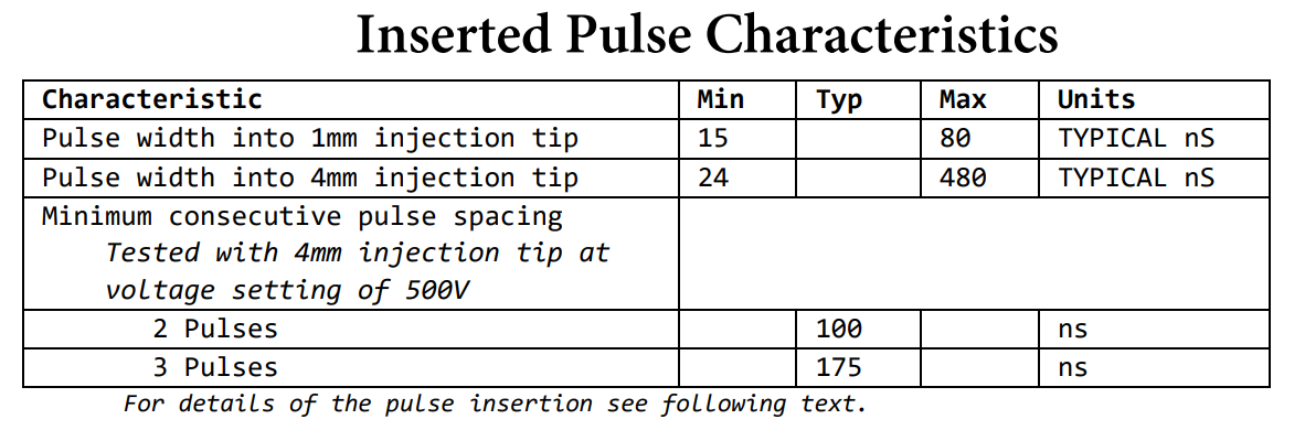
However the EM pulse that CS can generate from this is limited by physics. Setting scope.glitch.repeat = 500 will definitely not give you a 25000ns EM pulse! Have a look at the “Inserted Pulse Characteristics” of the CS user manual.
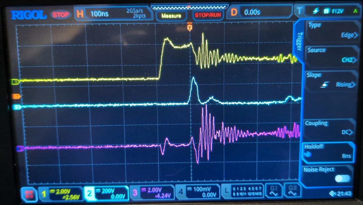
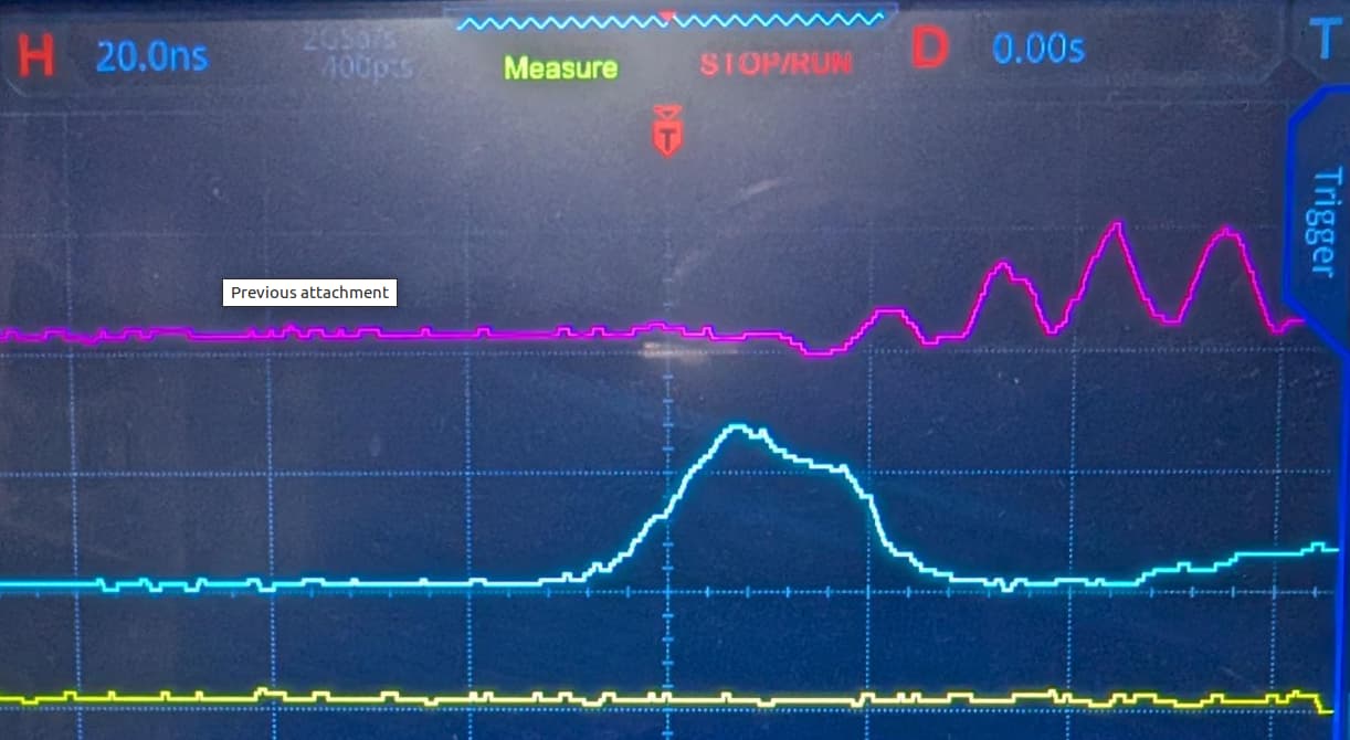
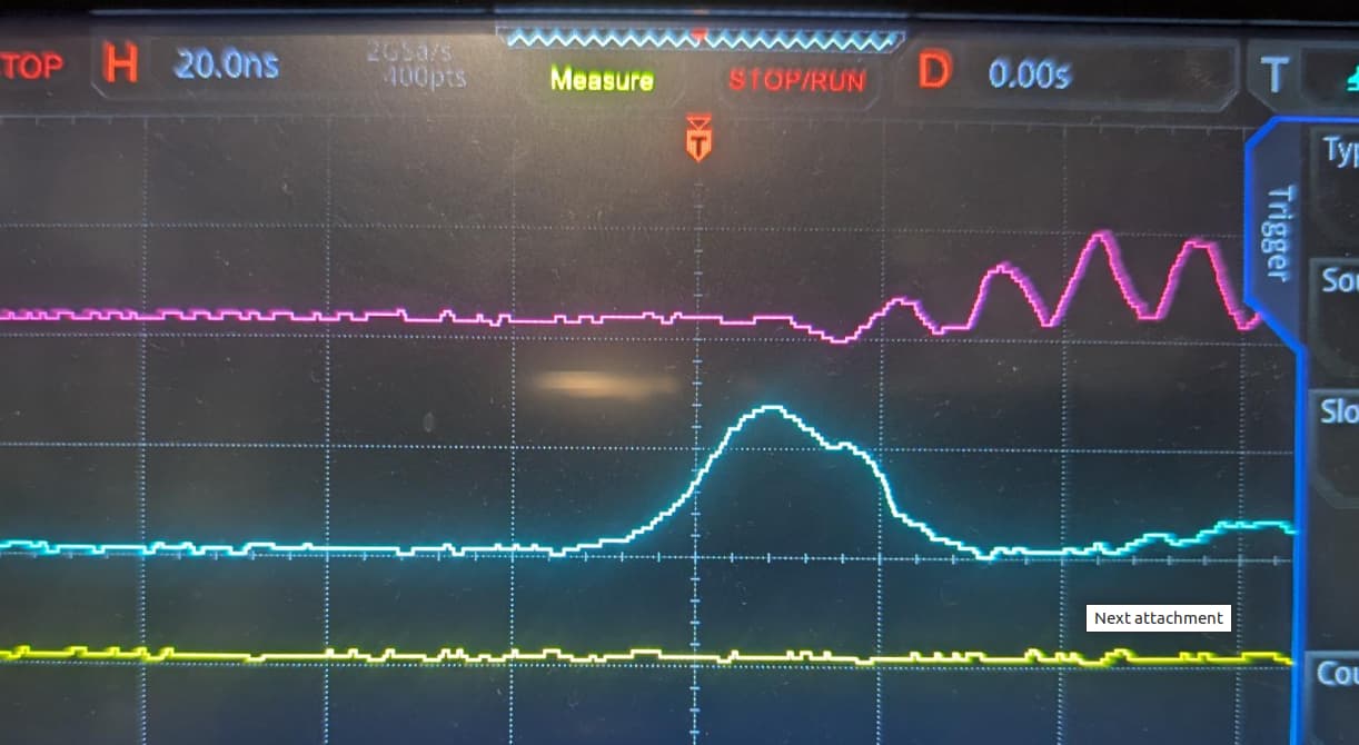
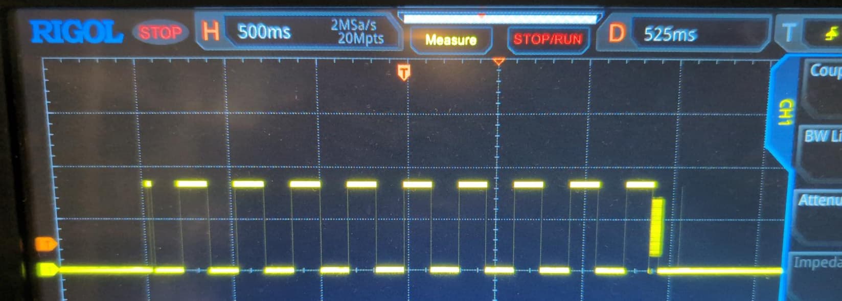
So I played with the changing the scope.clock.clkgen_freq from 20Mhz (50ns pulse) down to 60Mhz (15ns) pulse and I couldn’t get it to change the pulse width. I tried 40MHz to see if I would get at least half the size of what I had but I see no change. The images below show the a example of two of the settings I tried.
The other problem which could be related is that after the pulse is sent I end up with the following latched faults [‘fault_trigger_error’, ‘fault_trigger_glitch’] which I then manually reset by holding the arm button down for 8 seconds. I’m not sure why this occurs as the chipshouter is armed, there should be only one pulse to glitch for the observed trigger based on the trigger settings I’m using:
    scope.trigger.triggers = 'tio4'         # This is the I/O pin 4 we will be getting the trigger signal from
    scope.trigger.module = 'edge_counter'   # Choose how to trigger, in this case its based on the number of edges
                                            # we see i.e. like a clock
    scope.trigger.edges = 1
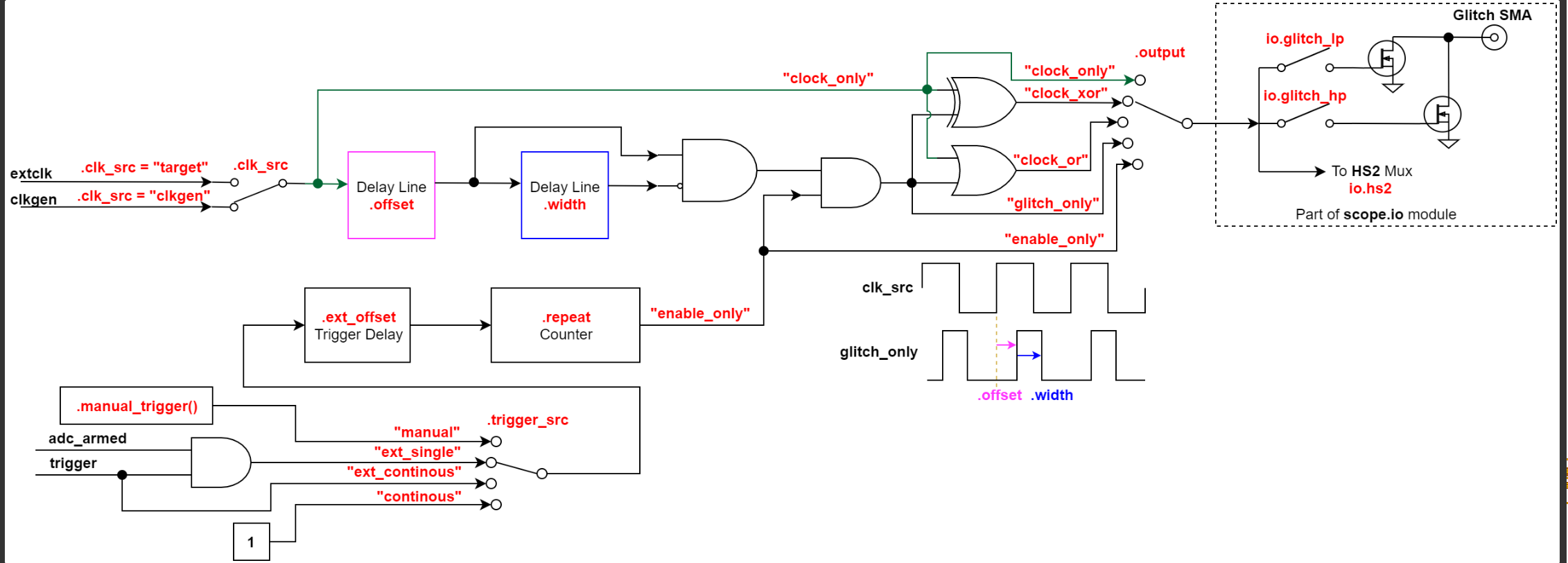
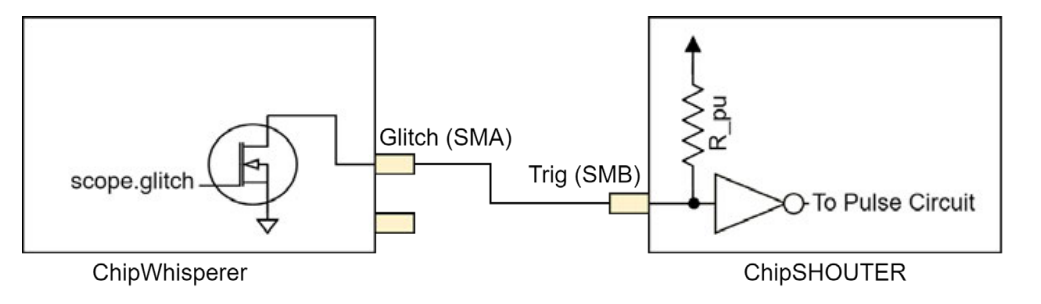
From the code I’ve been using it looks like I’m using the MCX connector, but also enabling the crowbar SMA connector?
 scope.io.glitch_trig_mcx = "glitch"     # Setup the MCX on the husky to output for a glitch
    scope.glitch.enabled = True             # This enables the glitch module
    scope.glitch.clk_src = 'pll'            # This is the clock source on the husky, so the offset and widths relate to this clock
    scope.clock.pll.update_fpga_vco(600e6)

    scope.glitch.trigger_src = "ext_single" # XXX ext_single in real use case
    scope.glitch.output = "enable_only"
    #scope.glitch.output = "glitch_only"
    scope.io.glitch_lp = True
But putting a probe on the Crowbar SMA port I get no signal…
I tried to just do a print(scope) but it gave the following error:
......
......
......
chipwhisperer/capture/scopes/cwhardware/ChipWhispererHuskyMisc.py", line 1337, in sampling_clock_frequency
    return self._scope.trace.clock.swo_clock_freq
           ^^^^^^^^^^^^^^^^^^^^^^^
AttributeError: 'NoneType' object has no attribute 'clock'
Since I don’t set a trace I’ve just printed out anything I’ve set, hopefully that has the information you need?
I strongly recommend that you go over the set of Husky demos there as they cover things specific to Husky that are not covered in our course notebooks.
Otherwise the glitch LED will flash whenever you generate a glitch (which is normal here), and the ADC light will flash when Husky’s PLL becomes unlocked (which can happen momentarily when you change something about Husky’s clock).
This is very strange. Can you share the full notebook which leads to this, so I can try to reproduce the issue here?
Thanks for suggesting the husky error page, I’ve added some specific print statements in and there is a “gain to low error”, reading the details on the error it looks like its more of a warning than a error (Scope API — ChipWhisperer Documentation).
I’m not using a notebook it’s just a python script, as I was just trying to keep it as simple as possible so I could understand, I’ve added in printing the specific errors and updated the output for you also. Hopefully it gives you some ideas for what could be causing the issue…
import chipwhisperer as cw

from chipwhisperer.common.results.glitch import GlitchController

from glitcher import Glitcher
from chipshouter import ChipSHOUTER
import time
import logging
import sys

port = "/dev/ttyUSB0"

def main():

    scope = cw.scope(name='Husky')
    scope.adc.lo_gain_errors_disabled = True
    print(scope.fw_version)
    print(scope.fw_version_str)

    # Setup the clock to use and what speed to run it at
    scope.clock.clkgen_src = 'system'       # "system" or "internal": An onboard crystal
    scope.clock.clkgen_freq = 40e6          # This is used for the glitching clock i.e. the higher the more accurate the
                                            # glitch occurs from the trigger The maximum is 200MHz (Husky)
    scope.clock.adc_mul = 1                 # Sets a new ADC clock frequency by multiplying this value by clkgen_freq
                                            # setting to 1 just leaves the clk freq at scope.clock.clkgen_freq
    scope.adc_test()
    # Setup what and how we are going to be triggered
    scope.trigger.triggers = 'tio4'         # This is the I/O pin 4 we will be getting the trigger signal from
    scope.trigger.module = 'edge_counter'   # Choose how to trigger, in this case its based on the number of edges
                                            # we see i.e. like a clock
    scope.trigger.edges = 1
    scope.adc.timeout = 2

    # Setup the chipshouter to glitch
    scope.io.glitch_trig_mcx = "glitch"     # Setup the MCX on the husky to output for a glitch
    scope.glitch.enabled = True             # This enables the glitch module
    scope.glitch.clk_src = 'pll'            # This is the clock source on the husky, so the offset and widths relate to this clock
    scope.clock.pll.update_fpga_vco(600e6)

    scope.glitch.trigger_src = "ext_single" # XXX ext_single in real use case
    scope.glitch.output = "enable_only"
    #scope.glitch.output = "glitch_only"
    scope.io.glitch_lp = True

    scope.glitch.arm_timing = "after_scope"

    scope.glitch.repeat = 1               # The number of glitch pulses to generate per trigger
    scope.glitch.ext_offset = [0,0]       # Only works with enable_only after the glitch module is triggered, it waits for a number of clock cycles before generating glitch pulses. This delay allows the glitch to be inserted at a precise moment during the target’s execution to glitch specific instructions.
    print(f"Offset: {scope.glitch.ext_offset}")
    #scope.glitch.offset = 500            # only works with glitch_only
    #scope.glitch.width = 500             # only works when glitch_only
    print(f"Phase shift steps: {scope.glitch.phase_shift_steps}")
    print(f"The glitch repeats: {scope.glitch.repeat}")
    assert scope.glitch.mmcm_locked         # ???

    print("Scope Glitch:")
    print(scope.glitch)
    print("Scope Trigger:")
    print(scope.trigger)
    print("Scope IO:")
    print(scope.io)
    print("Scope Clock:")
    print(scope.clock)
    # print("Sleeping")
    # time.sleep(2)
    # shouter = ChipSHOUTER(port)
    # print(f"Clear and ARM: {shouter.clr_armed}")
    # while not shouter.trigger_safe:
    #         continue
    # shouter.voltage = 400
    # print(shouter)

    # shouter.faults_current = 0
    # print(f"Faults latched: {shouter.faults_latched}")

    # if shouter.faults_current != 0:
    #     exit(-1)

    scope.sc.arm(False)
    scope.arm()
    print("ARM Scope and glitcher")

    # if not shouter.armed:
    #     shouter.armed = True
    #     print("Chip shouter not armed, arming")
    #     time.sleep(3) # wait for arming of chipshouter
    print(f"Start Capture timeout (sec): {scope.adc.timeout }")
    if(scope.capture()):                        # Blocks until scope.adc.timeout reached or matching signal found at scope.trigger.triggers
        print("Timeout occurred no edges seen")
    else:
        print(f"Edges seen: {scope.trigger.edges_seen}")

    print(f"XADC errors: {scope.XADC.status}")
    print(f"ADC errors: {scope.adc.errors}")
    print(f"Extclk errors:{scope.clock.extclk_error}")
    print(f"Trace errors {scope.trace.errors}")
    print(scope.errors)

    scope.dis()                             # Disconnect from the Husky

    exit()

if __name__ == "__main__":
    main()
The full output, note the error occurs from calling the scope.trace.errors.
I’m sorry this is taking so long to resolve. There are (at least!) two issues here:
You can’t access scope.trace.errors because scope.trace appears to return None. This is not normal. What version of ChipWhisperer are you using (cw.__version__)? Have you modified ChipWhisperer’s Python source code in any way?
You have said that you can’t create a proper single pulse output on Husky’s Trigger/Glitch Output MCX whose width is controlled by scope.glitch.repeat. I’ve not been able to reproduce that; it works exactly as expected for me. Please share code which reproduces the problem that you’ve seen.
Please no need to apologies, thanks for providing so much guidance and help.
I’ve using version 5.7.0 as I didn’t want to change to 6.0.0 while I was sorting out what was happening. I’ve not made any changes to the chipwhisperer lib.
>>> import chipwhisperer as cw
>>> cw.__version__
'5.7.0'
I’ve just been using the code from above the only changes that I would make is either making changes to scope.clock.clkgen_freq = 40e6 increase/decrease to change the pulse width with no change observed. Or I would increase/decrease scope.glitch.repeat = 1 but I wouldn’t see any change on the scope.
I’m just away from the setup for the next few days but I will double check when I get back.