We are trying to perform an attack on Arduino by using Chipwhisperer-Lite. We got all the connections and the SimpleSerial protocol working. We use the following code to capture the traces:
from tqdm import tnrange
ktp = cw.ktp.Basic()
n=1000
traces =
textin =
subkey=
project = cw.create_project(“projects/TracesCWandArduino”, overwrite = True)
for kguess in tnrange(0, 256):
subkey.append(kguess)
for i in tnrange(n, desc=‘Capturing traces’):
text = ktp.next_text()
textin.append(text)
And the following code to attack:
import chipwhisperer as cw
import chipwhisperer.analyzer as cwa
project_file = “projects/TracesCWandArduino”
project = cw.open_project(project_file)
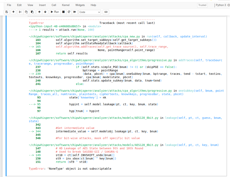
We get the following error when we run the attack:
error TypeError: ‘NoneType’ object is not subscriptable
Please see the attached file for more details on the error.
Thanks, that worked. We’ve also fixed an error regarding the key length (in our example a variable called subkey). I wonder why do we need to assign a value to the key when we create object Trace? Isn’t the whole point of the attack to find the value of this key?
We don’t have any errors now, but CW is unable to find the correct key. We’ve ran the attack for 5000 traces and used two different attack types (sbox_output and last_round_state_diff), but neither one of them was able to find the correct key.
The only thing that occurs to us is that perhaps the traces are too noisy. Is there a way to check if the power traces recorded by CW501 differential probe make sense?
Or is there something else we might be doing wrong?
The key is mostly used to highlight the correct key in the jupyter callback and the analyzer plots. If you don’t set it to None, you need to set it to a valid AES-128 key.
Are you running software or hardware AES? Also, what modifications have you made to your target for side channel analysis?
Thanks for your answer.
We are running AES on Arduino’s Atmega328P controller, so it is a software version of AES. We placed a small resistance between the 9V battery and Arduino’s Vin pin, and we placed a differential probe CW501 over the resistance. The output of the probe is attached to MEASURE port on CW-Lite. We’ve tried two resistance values: 0.01 Ohms and 0.1 Ohms, but neither one of them led to the correct key.
Any thoughts?
You’re probably not getting anything because of the small value of the resistance, the voltage regulator after the resistance, and the decoupling capacitors on the board, assuming you haven’t removed that. Try feeding in your own voltage, or at least measure after the voltage regulator, and remove all decoupling capacitors from the Atmega328p. I’d recommend 50ohms as a starting point for a shunt resistor.
You can use the differential probe here if you want, but the measurement port on the ChipWhisperer is already AC coupled, so you won’t really gain much over just using measuring the low side of the shunt unless your input voltage is very unstable.
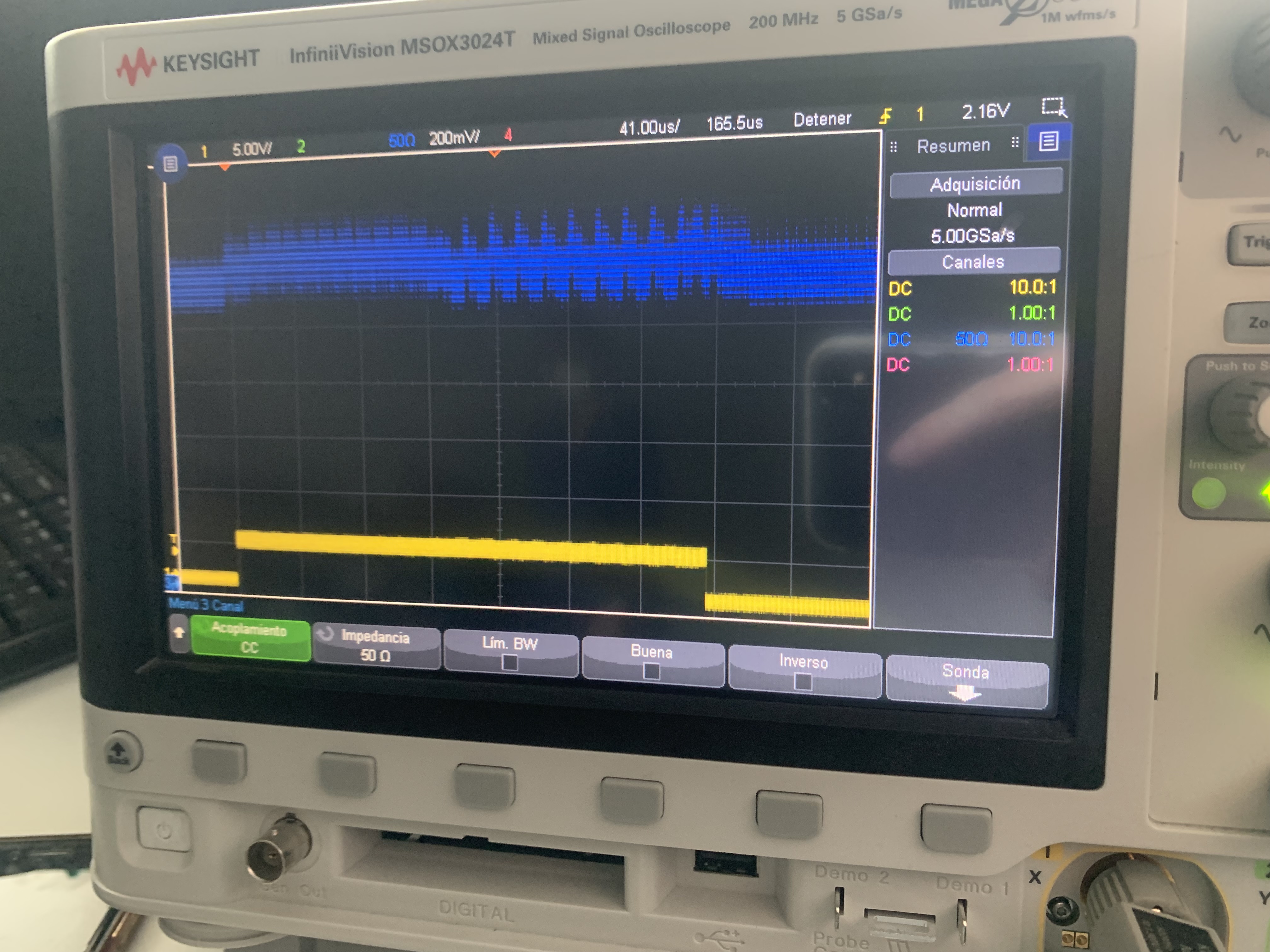
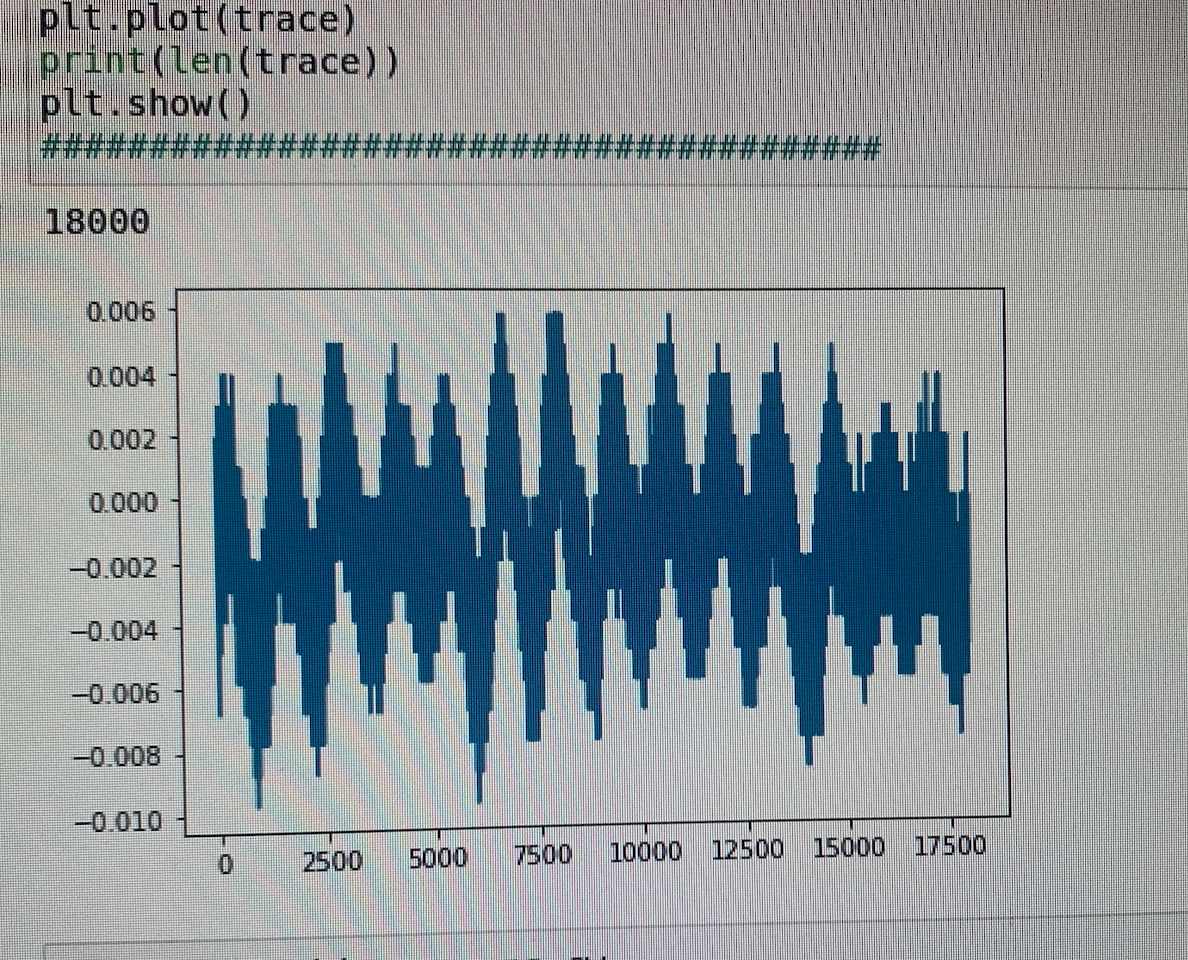
Thanks for your help. We put the resistance of 100 Ohms between the Atmega328P 5V pin and the voltage regulator and the traces look much better when we look at them on the oscilloscope (we’ve tried first with the 50 Ohms resistance, and doubled it to get better resolution). They look like this:
We checked the ADC sampling rate and it is 4 x Arduino’s system frequency. Also, we changed the number of samples to record so that it is similar to the result of scope.adc.trig_count(). We are using ADC gain of 40.
Could you please tell us if there is something we are missing?