i am trying to perform an attack on smart card but traces are too much noise please help about it
One way to deal with noise is to collect more traces.
High-security smartcards are protected against power analysis; you’ll waste decades collecting the necessary traces. Of course, there are alternatives available that can accelerate the attack, but they cost a fortune. I’d aim for the RSA5065N-OCXO spectrum analyzer. Remember, this is just one of several high-security smartcard security features, and there are usually several to further complicate and hinder the attack. The RSA5065N-OCXO mentioned in this example can be used to eliminate noise before the signal from the card reaches the oscilloscope’s ADC or chipwhisperer ![]()
i know very well about smart cards but its possible to get keys with power analysis and Glitch attack. Mark my words one day i will show u how get keys from smart cards
@Alex
The problems I mentioned concern cards that protect premium content. They are significantly more secure than Java cards used to protect door locks and the like. Such cards typically employ at least several advanced security measures and are not as easily faulted by glitches as today’s microcontrollers, such as the ESP32 or RP2040. The RP2350 is a step forward, but individual tests have shown that EMFI glitches still operate, but within a much narrower range, so the sensor controlling them isn’t as precise as those found in today’s high-security smartcards. I’ve tested various glitch modifications on today’s smartcards, but unfortunately, I haven’t found a working solution yet. I still have a few ideas I haven’t had time to test. I’m referring to cards from 2010 and 2020.
@Alex If you’re starting with Power Analysys smartcards, you should start by building a hardware clock recovery module. This is the first step. This will give you greater control over the smartcard. For this purpose, you should use an FPGA with a DAC, or ideally, a ready-made SDR. This mechanism shouldn’t rely on a narrow Chebyshev or Butherowrth filter, because smartcards have a highly desynchronized clock. An FPGA FIR filter should be used here. The FPGA with an SDR can then be used to build the rest of the clock recovery modules.
After a year of my experiments:
-
SLE88FX/CX (customized versions) - I managed to bypass the brown-out detector glitch, but the core was still able to detect glitches, suddenly freezing the card’s execution program. I’m 100% sure of this and can confirm it, so it’s a big step forward. The smart card’s production date is around 2010.
-
Some Atmel processors. I suspect it’s one of these processors: AT90SC 144 144T (customized versions) - unfortunately, I haven’t been able to find anything. The brown-out detector is unbeatable for me at this time. The smart card’s production date is around 2010.
Customized versions - these smart cards are custom. You can find Infineons with the same designation on the market, but they won’t be the same.
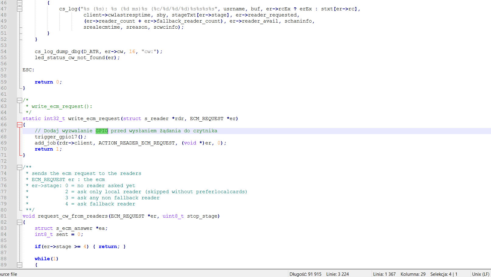
For my applications, I temporarily used the SmartLeia project, which had some bugs, and I had to fix the code. I had to add additional clock control and a few other peripherals for the trigger, and it worked. It generated glitches for testing on the ATR loop. This was enough for me to confirm whether the glitch was working or not. However, after some time, I decided that in the future I would need something more low-level, and with the added benefit of an FPGA, I chose the RP2040, or even better, the RP2350. My time is limited now, and if I return to this, I’ll do it slowly from time to time, of course, just for fun and learning.
I haven’t tested Power Analysys yet, but I’m convinced that these cards will require a clock recovery mechanism in conjunction with the SAD trigger.
SLE88FX/CX (customized versions) - I managed to bypass the brown-out detector glitch - glitch passed to core but was still detected. the glitch filtering circuit on the VCC line has been omitted by me.I can assume that this is some kind of second additional sensor.
It would be interesting to see your results. But I afraid, existing HW implementation of cryptographic algorithms, at least, AES is masked on modern smart cards. Even if you collect well aligned traces you will not able to recover the correct AES key.
I already faced with masked implementation. There are perfect traces, AES is also perfectly visible…but the key is not recoverable.
I haven’t reached the stage you’re describing yet. In my case, the main problem is the enormous noise added as SNR security. I’ve already largely cleaned up the power line by using optocouplers, but the AES example is still significantly noisy. I suspect the Infineon doesn’t use noise as security at all because it’s sufficiently protected in other directions (duel rail logic and other things). I also don’t think the masking implemented in 2010 is particularly impenetrable. My current target isn’t an Infineon; in the past, I’ve only practiced glitching on an Infineon, but I’ve seen traces that look clean and noise-free, which only confirms my suspicions. ![]()
The photo I attached shows AES128-CBC after initial cleaning, which is still quite noisy. It is also clear that the algorithm peaks do not directly indicate AES rounds, but some kind of curved implementation with additional security ![]()
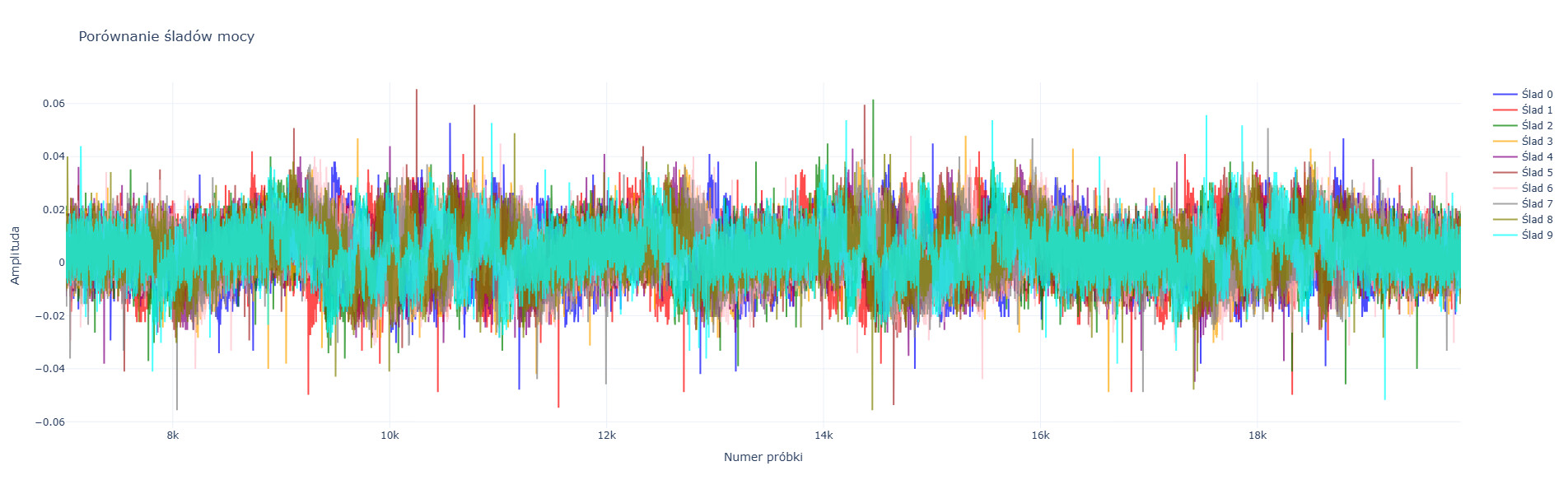
What is even more strange is that the traces contain minimal jitter, which they shouldn’t - the DUT clock is synchronized with cwlite in this case, this DUT doesn’t use either PLL or internal clock generator, maybe it’s a defect of cwlite, I don’t know.
After extensive experimentation, I observed masking and shuffling occurring on my 2010 smartcard. For example, the AES itself is fragmented and scattered over time. I only see the beginning of the AES, where 1-2 rounds should occur, while the remaining rounds occur at very long intervals. From what I understand, this is one of the strongest security measures available, apart from the noise itself, which I was able to remove by 30%. Is masking and shuffling breakable?
Cracking these security measures is impractical. It could be compared to verifying the same function in a loop 5-7 times. As a glitch prevention measure, the attacker would have to build a single, precisely timed payload with multiple glitches, where each glitch would have to land precisely at a specific location. If a random clock is added to the security measures, executing such an attack is very difficult, but not impossible.
There are several different variants of masking and shuffling implementations, some of which are crackable in 2025. The main problem is the shuffling length. I don’t know the exact level of security I’m using; it was a simple test on my part. I doubt I’ll expand on this further. If you’re using only masking, you’re in luck ![]()
![]() Finally, I’ll add that most smartcards are protected against differential measurements in 90-95% of their software-level functions. Even if you can crack the masking, the card won’t allow you to execute multiple instructions on different plain text/cipher texts or with a variable key. In short, for smartcards, you need working glitches—they’re more important than any differential measurements. The problem is that they don’t work on cards manufactured after 2010. Someone may have found a working glitch, but it’s definitely not Crowbar, the Clock glitch, or even EMFI.
Finally, I’ll add that most smartcards are protected against differential measurements in 90-95% of their software-level functions. Even if you can crack the masking, the card won’t allow you to execute multiple instructions on different plain text/cipher texts or with a variable key. In short, for smartcards, you need working glitches—they’re more important than any differential measurements. The problem is that they don’t work on cards manufactured after 2010. Someone may have found a working glitch, but it’s definitely not Crowbar, the Clock glitch, or even EMFI.
That’s all I wanted to add if anyone thinks that even the oldest smartcards manufactured after 2010 can be cracked with a relatively simple method. Of course, this was just an experiment to confirm my speculations.
Did you try other smart cards? Say from late 90’s or early 00’s. They definitely had much less protection against side channel attacks.
One more question, how did you trigger trace capturing? Did you bind to the specific APDU.
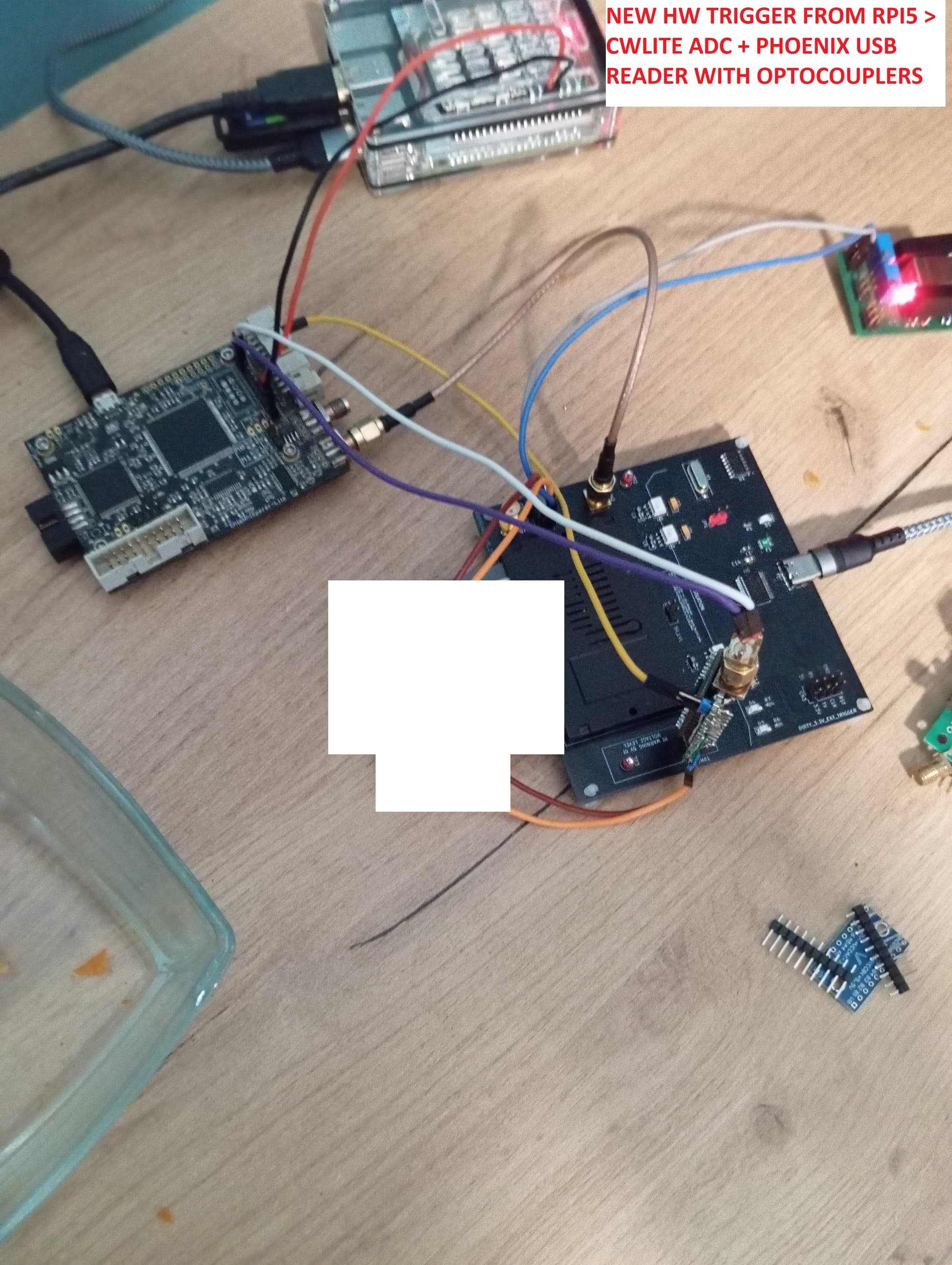
I have everything running on a Raspberry Pi 5. An application is installed on it that controls the smartcard and sends a trigger signal to the chipwhisperer. Very little time elapses between the execution of an instruction on the smartcard and the trigger being triggered, so this behavior is appropriate. The smartcards I tested are very old, and I partially compared their behavior with newer ones. In the older smartcards, I encountered protections that resemble masking mixed with shuffling, because the AES128-256 RSA Diffie-Helman operations are interspersed and scattered in the differential analysis graphs and contain a lot of noise. Newer implementations have significantly less of this noise. All implementations, both older and newer, do not respond at all to voltage, clk, or emfi glitches. These protections are a task for someone with significant differential measurements experience.
My application, when sending an instruction to the smartcard, sends a trigger to the chipwhisperer - this is the best way to do it, I also trigger glitches on different processors in a similar way, my trigger is associated with an instruction request.
The biggest difference between old smartcards and new ones, which can have a big impact on the security level, is the clock line. In old smartcards, the iso_clk clock is completely synchronized with the internal HW, in new smartcards it only synchronizes during init, then you can disconnect it and the smartcard continues to work on its own internal clock. If you have access to the smartcard’s clock synchronization, you have an easier way to break masking shuffling and to synchronize glitches if they work.
Do you use an extension board? It is not clear how do you measure the VCC line, what voltage you apply on your card, what shunt you use to measure changes on the VCC line, how good is your syncronization to trigger on the specific event, etc…
The picture I saw from your previous comment is really bad, no chances to get something from it.
I would recommend to learn on NXP Jcop cards which are available unfused and non-personilized. So you should have rich capabilities with SCA attacks on these cards.
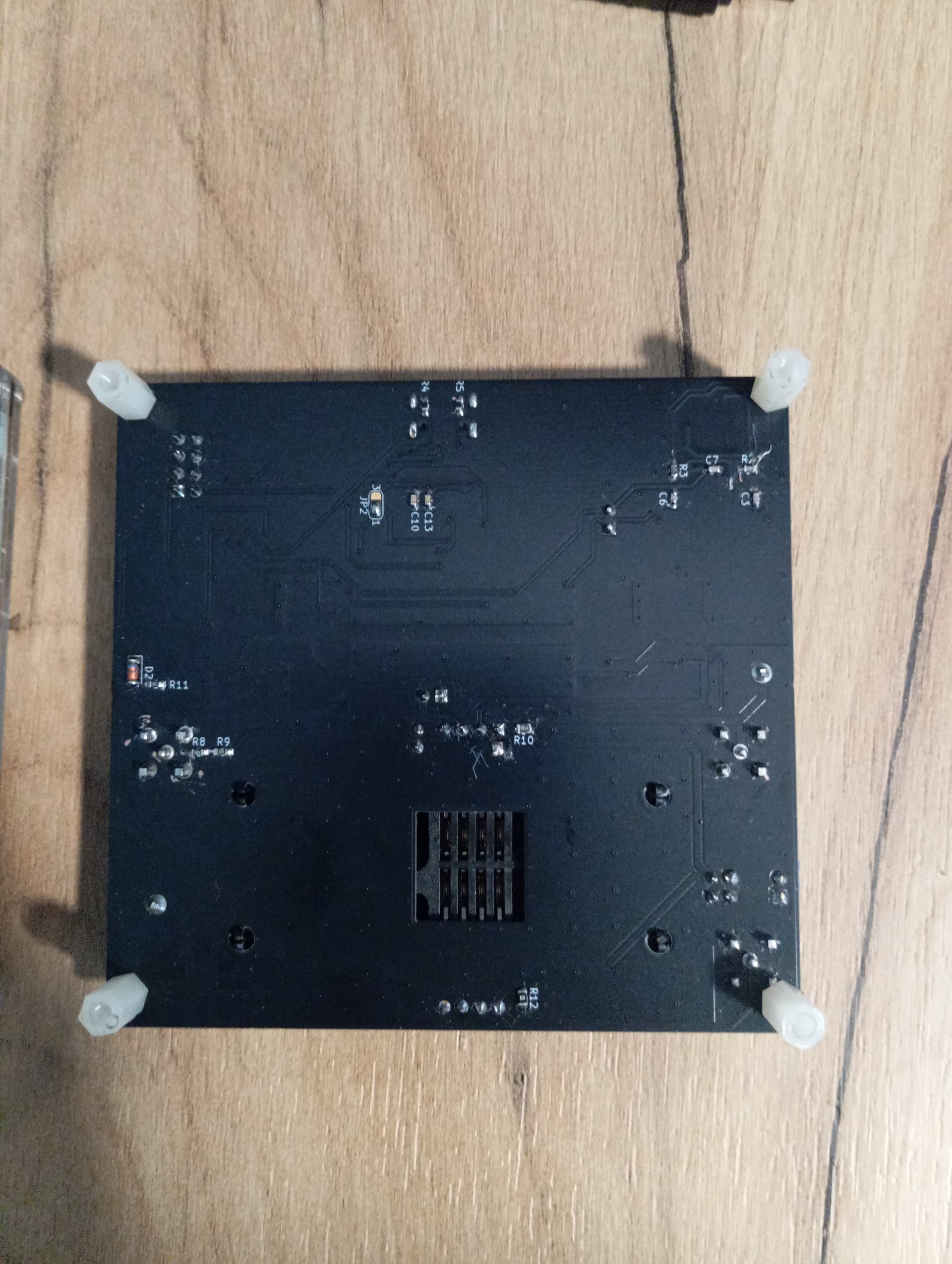
At the beginning, I used the SmartLeia code from hw on a universal PCB, but this solution turned out to be not very universal for me. In the next stages, I built a PCB - it’s a phoenix serial interface with added FOD8001 optotriacs + shunt + sma connectors and much more.
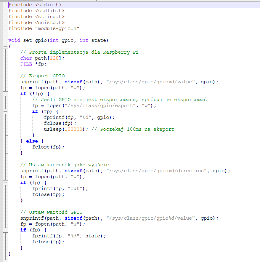
How does it work? The modified oscam, when performing cryptographic operations related to the smartcard, generates a HIGH pulse which is received by cwlite_adc > then the measurement is performed. The moment of transmitting the pulse is very fast (sufficient), a small minimum jitter is introduced (1) - if the smartcard works on an external clock and synchronizes with this clock, the jitter is only 0.1ps.
- Init smartcard in oscam installed on RPI5 > during init generate pulse trought RPI GPIO > optocoupler > CWLITE_ADC . During init, the trigger handle is paired with individual cryptographic operations of the 2nd smartcard. It is operated directly through the serial port usb_ft232rl = oscam, it does not need any microcontroller for communication. In my case, the trigger is sent when the encryption is requested and it works very quickly and accurately. 3. In your case, if you only have masking in use on the smartcard, you can apply the trigger directly from the aes rounds using the SAD trigger, in my case it was impossible because the smartcard used “shuffling” in addition to masking. This algorithm cuts the encryption waveform into pieces and spreads them over time to make triggering and differential analysis more difficult.
2010 year high security smartcard vs. medium or low security Java smartcard is a big difference
Yes, I know NXP Jcop cards but I don’t have time for such fun anymore or for what I described. I have other goals.
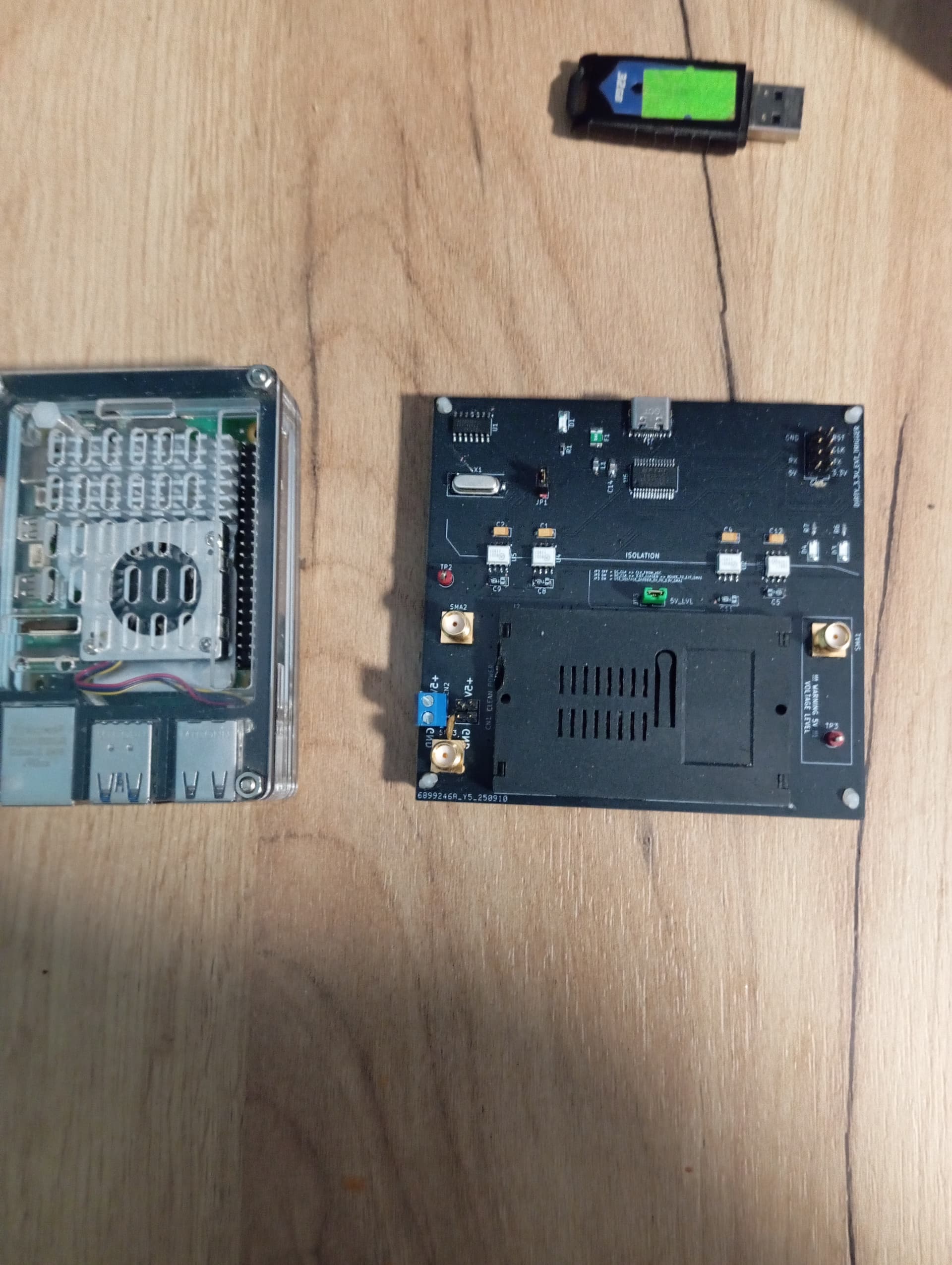
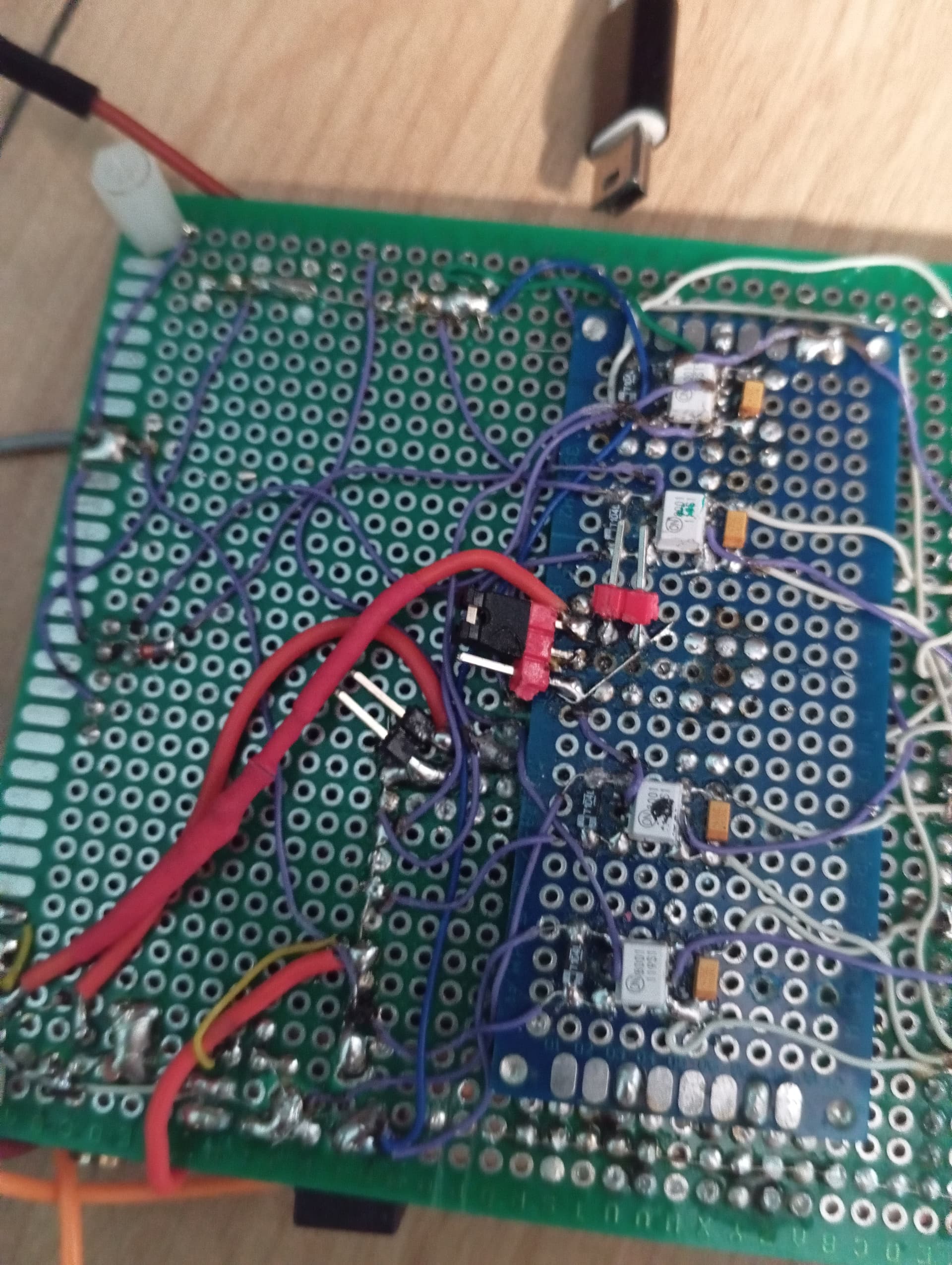
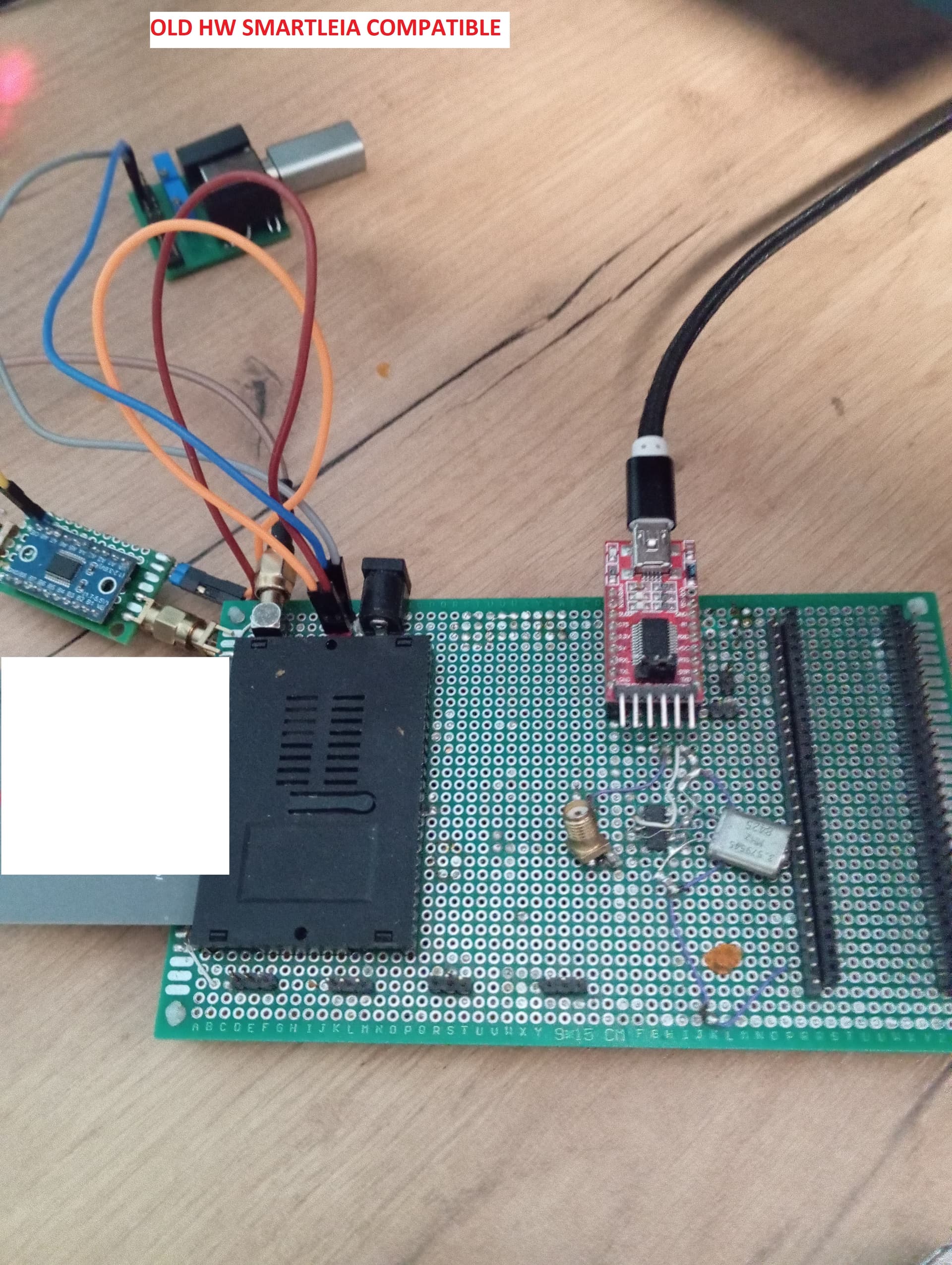
From what I remember, I used a 0.1 ohm 0805" resistor recommended by the smartleia team. I used wiringpi as a trigger. The photos show an example of using the trigger as a handle before or when ECM is allowed to attach to the smartcard

I was testing for fun, I don’t have time to continue this fun anymore.