I would like to have an explanation of the trace shown in the image related to the AES-128 encryption algorithm on the lab (CPA on Firmware Implementation of AES)
1- Where Are the 10 Rounds?
2- What Does the X-Axis Represent?
I would like to have an explanation of the trace shown in the image related to the AES-128 encryption algorithm on the lab (CPA on Firmware Implementation of AES)
1- Where Are the 10 Rounds?
2- What Does the X-Axis Represent?
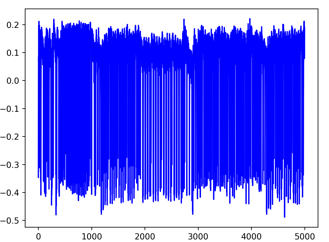
The x-axis are the power trace samples. ChipWhisperer samples at the rate indicated by scope.clock.adc_freq.
You didn’t say which target you’re using. Each target will have its own distinct power traces, even if it’s using the same AES source code. But this likely is only showing a subset of the full AES encryption. After running an encryption, scope.adc.trig_count will tell you how many samples the trigger line was high for, which tells you how many samples the full encryption takes.
(The reason our AES CPA notebook doesn’t capture the full encryption is that it is targeting the first AES round only.)
I use chipwhisperer husky with
1- PLATFORM=“CW308_SAM4S”
2- CRYPTO_TARGET=‘TINYAES128C’
3- SS_VER=‘SS_VER_2_1’
And I use “CPA on Firmware Implementation of AES” lab. Did you mean this lab only focused in first AES round only. Or it make all 10 Rounds and only capture the first round for analysis.
This attack uses leakage from the first AES round only. The target is performing all 10 rounds, but the attack only needs power traces from the first round.