Hi, as previously announced, I’ve started working on a custom board for the SPC58 to use with CW308. Anyone who wants to contribute, suggest modifications, or validate my work is welcome. Designing electronic boards isn’t my job, so there will likely be errors or mistakes.
Thanks to everyone who wants to help me.
This is the PDF of an evaluation board that uses the same target device, SPC58NN84 in QFP176 package. This microcontroller is one of the stronghest out there, is ASIL-D Automotive.
steval-ttm004v1_schematic.zip (501.7 KB)
ON CW308-MPC5777C schematic there is a LDO to generate 1.2V for VCCINT, why there is the LDO on the target board even if there is a 1.2V power source from CW308 board?
Thanks for sharing! We wanted to add some links to community targets as well, that was on a long TODO list…
To answer your question on the design, the VCCINT is this here:
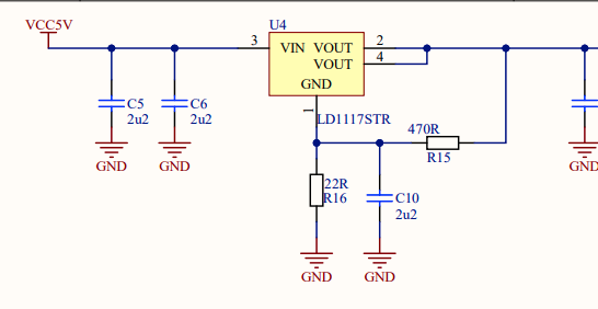
This is actually set to 1.3V - the reason being the internal regulator for these devices is trying to regulate to 1.2V, so by having the voltage well above the setpoint the regulator wont’ try to turn on any outputs (can help reduce noise). This is a little from memory though as I haven’t looked at this device in a while - but we often use a trick of “slightly over-powering” the core voltage on targets to disable/bypass their internal regulators.
I can’t remember if this one actually had the internal regulator (or used an external transistor), but it might have been just a default “safe” choice to ensure the regulator control circuitry was in a constant state. When doing SCA with our resistive shunt at 1.2V, the problem is you can get the voltage dropping in/out of a region where the regulator is turning on/off. So we go a little higher so even with the resistive shunt drops it still stays above the 1.2V shut-off.
Thanks Colin, I had an idea it was something similar, but not having advanced knowledge on the subject I wasn’t sure
Good morning everyone, I’m attaching the first schematic of the board. Could someone please check if any problems are visible? Are there any improvements that can be made? Can the number of capacitors be reduced (the power supply branch comes from the evaluation board)? I’ve introduced several jumpers and R0 resistors so that it’s easy to isolate parts of the circuit. VDD_LV are all open jumpers so that power can be gradually applied and improve the possibility of faults.
CW308-SPC58.zip (139.3 KB)
Thank you in advance for your support