CW Husky and communication with a smart card

Hello.

I am interested whether “serial_tx_rx” works for CW Husky to work with the smart card in the half duplex mode.

The FPGA UART module can be configured as

target.ser.cwlite_usart.init(baud=19200, stopbits=2, parity="even") and it works fine. I am able to get an ATR.

The unclear thing is whether below parameters works as I expect - to work in the half duplex mode to send and receive APDU messages.

scope.clock.clkgen_freq = 7142857
scope.io.hs2 = 'clkgen'
scope.io.target_pwr = True
scope.io.tio3 = "serial_tx_rx"
scope.io.tio1 = "high_z"
scope.io.tio2 = "high_z"

I definitely able to receive data (ATR response) but I am not sure whether data can be transmitted to the smart card side (the card doesn’t respond on the message to be sent). The only TX echo is received.

So my question is whether “serial_tx_rx” configures Husky’s FPGA to use a single wire SC_IO to talk with the card or my understanding of serial_tx_rx is incorrect? Or this functionality is just broken?

More likely serial_tx_rx doesn’t implement open drain which causes collisions on the IO line. The echo bytes are slightly damaged and one byte is missed. So the card just wait for the data and doesn’t respond.

Thanks for noting this. While we considered smart card support a long time ago, we decided against it.

We forgot to remove the serial_tx_rx option from the API – it’s never actually been supported by any of the capture hardware (Lite/Pro/Husky). I’ve removed it now.

Thanks for the feedback.

One more question. What is the simple and reliable option to measure the smart card processing time in terms of internal Husky’s measurement unit (I guess the “trig_count“ value)?

Suppose I want to measure the “smart card processing“ interval [ APDU message … 55 AA ] [ smart card processing ] [ status word 90 00 ]. Do I need to setup the UART trigger for the 55 AA pattern first and then to use the arm and capture functionality? If so, how to stop counting of the “trig_count” on getting the start bit of the first status word byte?

scope.adc.trig_count only counts how many cycles the trigger line is high, which is only really useful when using scope.trigger.module = “basic”.

The UART trigger is like any other trigger: you arm the scope, and the trigger (whether UART or whatever else) triggers the capture.

It’s not clear what you’re trying to do, but Husky doesn’t have the ability to count cycles starting from a UART trigger event.

@jpthibault

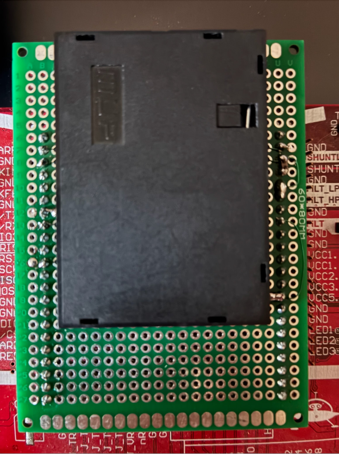
I built such smart card extension which works very well. I am able to communicate (RX/TX) with the smart card using standard 20-pin cable and capture the power traces. The quality of the power traces is perfect. I didn’t expect to see high quality traces using just a prototype.

The things are interested to me are:

  1. UART triggering and capture the traces.
  2. UART triggering and measuring the interval between smart card request and response.

The first thing is conceptually more or less clean but the second thing is not so obvious.

Suppose, I send the message to the card [ SC message: XX XX XX XX XX 55 AA] [ SC processes the message ] [ SC replies: 90 00 ]

The goal is to measure this interval [ SC processes the message ]

Should below setup work? Briefly, the idea is to capture the last byte (0xAA) of the payload echo from the Husky TX line to trigger the UART trigger on the Husky RX line so that to run the logic analyzer to capture activity on the RX line. The main goal is to detect the start-bit of expected answer 0x90 and then calculate the number of Husky ticks between the trigger and the start-bit.

For unclear reasons, the UART trigger doesn’t fire on getting 0xAA. Maybe this configuration affect UART triggering? target.ser.cwlite_usart.init(baud=19200, stopbits=2, parity=“even”)

    scope.io.tio1 = "serial_tx" 
    scope.io.tio2 = "serial_rx"
    target.ser.cwlite_usart.init(baud=19200, stopbits=2, parity="even")

    scope.clock.adc_src = "clkgen_x1"
    scope.io.target_pwr = True
    scope.clock.reset_adc()

    scope.trigger.module = 'UART'
    scope.trigger.triggers = 'tio2'
    scope.UARTTrigger.enabled = True

    scope.UARTTrigger.set_pattern_match(0, [0xAA])
    scope.UARTTrigger.trigger_source = 0


    scope.LA.enabled = True
    scope.LA.capture_group = 'CW 20-pin'
    scope.LA.clk_source = 'target'
    scope.LA.oversampling_factor = 1 
    scope.LA.capture_depth = 1000
    scope.LA.trigger_source = "capture"


def run_timing_analysis():

    payload = [0xXX, 0xXX, 0xXX, 0x55, 0xAA]
    apdu = [0xXX, 0xXX, 0xXX, 0xXX, len(payload)] + payload + [0xXX]
    
    scope.LA.arm()
    scope.arm()
    target.ser.flush()
    
    print(f"TX: {' '.join(f'{b:02X}' for b in apdu)}")
    target.ser.write(apdu)
    
    ret = scope.capture()
    if ret:
        print("[-] Error: trigger timeout")
        return

    raw_la = scope.LA.read_capture_data()
    io_rx = scope.LA.extract(raw_la, 1)


    try:
        # processing
    except IndexError:
        # processing

…forgot to mention that the smart card implements IO as an open drain. So I used the BAT42 diode to connect Husky’s UART and IO SC. Cathode is connected to Husky TX, anode is connected to the Husky RX, IO SC and pulled up via a resistor 4.7 kOm to VCC.

You need to specify the baud rate, stop bits, etc… to scope.UARTTrigger.

Unfortunately, you cannot use scope.LA and scope.UARTTrigger simultaneously.

Thanks. It works after removing the logic analizer from the settings and adding

scope.UARTTrigger.stop_bits = 2 
scope.UARTTrigger.parity = "even" 

So I don’t have any reliable options to measure time interval between a card request and a response except capturing the power trace to find the UART activity on the trace?

We’ll consider adding this capability in the future! However it’s unlikely to come to Husky, its FPGA is already quite full.

But this sounds like a very TIMTOWTDI case… in my experience, UART activity tends to be very obvious on a power trace. Alternatively, retain the ability to use scope.LA by using a different trigger, like edge_counter, or SAD.

Let me clarify one more question.

I found this solution works:

    scope.trigger.module = 'edge_counter'
    scope.trigger.edges = edges_needed
    scope.trigger.triggers = 'tio1'

    scope.LA.enabled = True
    scope.LA.downsample = 9
    scope.LA.capture_group = 'CW 20-pin'
    scope.LA.trigger_source = 'capture'
    scope.LA.capture_depth = 16300
    scope.LA.arm()
    scope.arm()

The problem is downsampling. To get more precise intervals I would like to reduce downsampling to 1 but capture_depth is too small for my task.

I am looking for an option to add an offset before LA triggering but cannot find it.

@jpthibault Is it possible somehow to use the offset functionality for the logic analyzer trigger?