Hello,
I have a board with XMEGA128 with 64 pins and I need to do some attacks offboard, I disoldered the QFN64 MCU from the board and soldered it in the QFN64 to DIP64 adapter so I have an easy access to all the Pins.
Can I connect the CW Lite Mainboard directly to the MCU on the DIP64 pins? I mean If I can connect the Clock and Vcc directly from the Mainbaord and use them to clock and Power the MCU without any additional components? Or should I add some components on the DIP64 adapter?
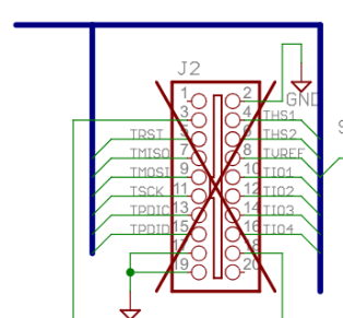
1- That is the latest schematic. The X’s are do not mounts.
2- Not quite. This will depend on your target’s requirements, and you can look at our target board schematics on https://rtfm.newae.com/ for inspiration and guidance. You’ll usually find some decoupling capacitors, a shunt resistor, etc…
Hi,
I also have got the doubt that Xs means Not Mounted, but almost all the Xa are present on the Target Board, see for instanc the Connector J2 can not be not mounted
So What is the X means here?
Also these schamtics are since 2015, is it the last version?
I need to use these schamatic for inspiration to adapt hte CW to my Target MCU…