I’ve been ramping up on CW-Lite - fantastic tool! I’m taking a look at VCC glitching the XMega victim board now. (I read through the clock glitching tutorial, but I wasn’t sure how it applied due to the differences between Rev2 and CW-Lite so I skipped testing it out.) I’ve tried to extrapolate the method from the Rev2 instructions, but I can’t seem to find the right sequence, and I’m afraid of frying something. Do you have updated instructions/tutorials for glitching on CW-Lite?
It does work for sure - but I’m still updating that tutorial! I’m on the road right now for CHES + SEC-T conference, but will try to take a look at this. Unfortunately I’m not sure I have the regular production hardware with me, so it’s hard to make a useful tutorial that I can confirm works (I’ve got some hardware, but I’ve got to check which revision it is).
For the XMEGA VCC glitching, I can suggest you can try following that same tutorial, but instead of using the “glitch adapter” you just need to enable the “low-power glitch output” checkbox.
For the clock glitching, you can use the settings described in the tutorial (I think). The hardware is equivalent to what is expected… the only main difference is you use the built-in “XMEGA Programmer” tool.
Getting the glitching working really needs some experimentation with settings via the glitch explorer, which isn’t documented right now (it was going to be part of the updated documentation).
I’ll try to get that updated ASAP though, as it may be a very frustrating experience if you try to follow the tutorials and I’ve missed something that is different!
I was just looking into this more… I forgot the firmware examples changed even, so the current firmware didn’t have that referenced code. I’ve fixed that now but will have to go through and update the docs a little with other subtle changes, so might be worth waiting.
EDIT: I’m having other trouble with using the release, so may indeed be worth waiting a bit for me to replicate!
Thanks for looking into it - no hurries, I know you were at CHES so I wasn’t expecting an immediate reply.
Yeah, I noticed the firmware mentioned in the tutorial was missing from the release (I’m using 0.12RC1) but I was able to replicate it pretty easily. My problem is that doing one of the steps to enable the glitcher seems to kill the XMega and it can take a while to get it working again, hence my fear about burning something out.
I’m very interested in the glitch explorer too, but first I just wanted to try simple manual glitches. I can definitely wait until you have a chance to take a look at it and replicate it.
It’s pretty normal to cause the XMEGA to stop responding and need a power cycle (or even reprogram) during the glitch testing. Which is what I assume you mean about killing it!
But I also see an error where when I adjust the glitch width/offset it is causing odd behavior in the FPGA. It uses some tricks to achieve the glitch generation, and I think one of them messed up… I don’t have a scope with me so hard to test it alas. These could also be the cause of the behaviour you see (since the FPGA isn’t responding correctly now), and the more I test it the more I suspect there was some error in the release w.r.t. glitch generation logic. The glitch generation logic has some special considerations as it uses the “partial reconfiguration” features on the FPGA, which is easier for me to mess up in the release…
FYI in the clock glitching thread, there was a post for the fix for the FPGA issue (originally thought you were the same poster, so didn’t double it back here!). It was indeed an issue in the release.
There is now a complete tutorial for clock glitching at newae.com/sidechannel/cwdocs/tutorialglitch.html . This also includes a video of the attack. You’ll have to use the CW software from GIT, or if using the instant chipwhisperer VMWare image just do a “git pull” to update. There were a few improvements in the Capture software for this tutorial.
The VCC-glitching one will follow. But the clock glitching lays a lot of the ground-work, especially in terms of how to use the “glitch explorer” for tuning parameters of the glitch attempt. Might get you going!
Thanks a bunch - I’ll grab the git version of the software and peruse the tutorial (which looks extremely detailed!). I saw the FPGA update in the other thread and tried it out, and indeed the FPGA stopped hanging on partial reconfig, but I wasn’t able to produce a successful clock glitch yet. I suspect it’s just the CW-Lite victim needing different parameters, so I’ll follow the tutorial. I’m eager to start beating on things with the Glitch Explorer!
Yeah, the XMEGA is a lot more finicky compared to the AVR for clock glitching. With the AVR you could “play around” until things worked… with the XMEGA you reallllly need the glitch explorer to save yourself a ton of grief, as you need to do a pretty detailed search of possible parameters.
Even after updating the FPGA and SAM3U images, I was still running into weirdness, so I decided to throw the CW-Lite clock output line on a scope. I observed the following when running in Clock XOR mode (with Continuous glitches so I could see them easily on the scope):
The coarse (%) Glitch Width setting seems to have no effect at all.
The coarse Glitch Offset setting has an effect - raising it narrows the high part of the clock waveform.
The fine Glitch Offset setting has the expected effect of moving the glitch through the clock waveform - but changing the coarse settings sometimes seems to cause it to not work.
I set the output to Glitch Only and verified that the coarse Glitch Width setting has no effect - the glitch is always ~34ns (the clock is 7.37MHz as specified in the tutorial). The fine Glitch Width does have an effect - setting it to 255 raises the measured glitch width to ~39ns.
Even without being able to set the Glitch Width, I was able to get a successful glitch on the XMega (jumping out of a loop) just by playing with the coarse and fine Glitch Offset settings. You’re right, it is pretty finicky!
Any ideas on what could be going wrong? I can run experiments if that would help. I’m currently running the code fresh from the git repo.
Hmm… damn, not sure what happens! That partial reconfig is going to kill me. However I was able to duplicate your error here, hold on while I try to track it down. Perhaps some other issues in the PR configured files or software.
On the downside I might need to update that tutorial again if it means some of my tests weren’t working correctly.
I really need to setup an automated test for the PR files, as it’s a nightmare if users need to track down issues like this (since some of them might not have a scope). Hopefully would avoid issues like you are seeing.
Update #1: It’s a combination of an old & new bug. The old is that sometimes when offset was set to 0%, the width setting wasn’t taken properly. I thought that was fixed but need to look into it more.
The new bug: there is a collision between the two pieces of partial reconfiguration data. In the LX25 device this didn’t happen, I need to spend some more time fixing it for the LX9 device. Will update once both are fixed.
Update #2: I’ve fixed the issue of overlap, but I did it using the “brute-force” method of generating every possible combination of offset + width for the DCM blocks. This means basically rather than being 256 x 2 combinations of PR data, there is 256 x 128 combinations. I’m working on generating the data, but need to parallelize it first. Otherwise it will mean ~ 2 weeks or so to generate the data(!). Luckily it’s super-easy to parallelize, but still may take a day or something, will have to see how fast my computer runs.
As far as automated testing of PR/glitching - Could you somehow loop the HS clock output to the ADC and compare against expected patterns with SAD? Would probably take a jumper cable now, but maybe with a loopback option on future revs of CW-Lite. (I’m not a signal integrity guy, so I don’t know if the on-board loopback is feasible/a good idea…)
I believe this is fixed now in GIT. It requires updates to both the .zip-file along with some of the software, so it’s easiest to pull down an update from GIT for now.
Right now the glitch “width” is limited to 0-37% right now. My scripts aren’t done generating all the new files yet, so I uploaded a temporary version for now. Once the scripts are done (another ~12 hours) I’ll push the firmware+PR data that again does 0-50% glitch widths. Unfortunately these scripts are currently still very slow (even running in parallel), so takes 3-4 days to run. I started a support case with Xilinx to solve the problem the “proper way”, which would be for them to give me a little more documentation on the bitstream format, and I wouldn’t need all these crazy scripts.
But all you should care about is that it is working - you’ll see some more commits as I clean everything up too. Let me know if you have trouble… I haven’t tried it on a clean install yet so I could have forgotten something!
EDIT #1: I tried this on the CW-Instant and all is good, so you should be good to use GIT. If using CW-Instant just do a “git pull” to get the fixes.
Awesome, thanks for all your work on this! I pulled from git this morning to try things out, and things are definitely looking up - I see the coarse and fine glitch width and offset settings modulate correctly when scoping the clock. I’ll pull again tomorrow to get the latest updates.
Unfortunately (or fortunately - you like solving problems, right?) a few new things cropped up as I got a little further in the clock-glitching tutorial. (By the way, let me know if I should start a separate thread or something, since the name of this one is no longer very accurate, but if not I can keep dumping info in here.)
When I changed from a Manual Glitch Trigger to an Ext Trigger, it seems that the Ext Trigger:Single-Shot doesn’t do anything. I put the clock and trigger (IO4) on the scope and looked at it, and when the trigger is set to Ext Trigger:Single-Shot, there are no glitches. When it’s set to Ext Trigger:Continous, I see the correct number of clock glitches a few cycles after the trigger (based on the name, I was expecting it to start infinite glitches).
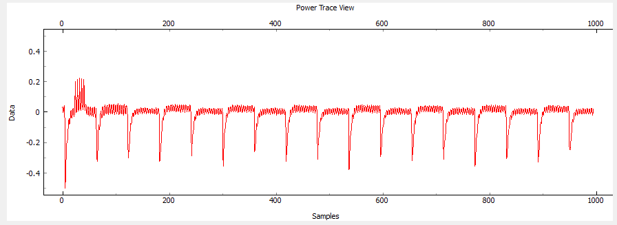
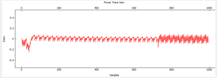
When I look at the ADC data of each capture (in the waveform panel), I see something unusual. Sometimes the data looks correct (similar to your picture in the tutorial, and exactly matching the output of the amplifier when scoped). Sometimes, though, it looks completely different. I don’t really know how to describe it, so I’ll get you a screen shot when I can. This made me think that maybe the trigger is not in the right place every time, but it always looks correct when I scope the trigger line and the output of the amplifier, and the scope is triggering on the rising edge of IO4 and doesn’t see any extraneous triggers either.
After quite a while of working in the capture software today, it started bringing up a window that says “Reading” (with a progress bar that never moves) whenever I get a capture. The software seems to work fine after this starts happening, it’s just a little distracting.
Thanks again, and let me know if there’s any way I can help (other than trying out new software).
Alright, thanks for the notes! BTW if you find other errors (or documentation fixes/errors) let me know too Some notes:
With the “single-shot” mode, it only “arms” the single-shot when you start a capture. Are you using the “Capture 1” for those? If not it will not generate glitches. You can also hit the “Manual/Arm” button, which “arms” the glitch, but still waits until the trigger for the glitch to be inserted.
The continuous mode doesn’t wait to arm anything, it always generates a glitch when there is a trigger pulse. So the continuous just means it will generate glitches all the time (when the trigger occurs)… this can get you intro trouble sometimes as the insertion of a glitch causes another trigger to occur, and you get an infinite loop. That’s why I added the “single-shot” mode. It’s a bigger issue in VCC glitching (when pulling the power supply down might generate the trigger condition).
It needs more documentation about what it’s actually doing, and the “continuous” name isn’t great either.
Hmm… haven’t seen that! Let me know if you get an example.
Not sure on that one either offhand - that’s in the OpenADC code, but should only happen if the USB connection is slow (which also shouldn’t happen!). If it happens again, try changing the number of samples out of interest (i.e. try 10000 instead of 1000 - does it take longer to record now?).
It seems to happen as frequently, if not more, than a regular waveform. I’ll try to scope the other inputs to the ADC to see if anything looks out-of-place when the odd waveforms occur.
Hmm… this is odd for me! I’ve been using that system to get a glitch without issue. I assume you are using the same rising-edge trigger too?
Let me think about how to debug that, as without being able to recreate it’s trickier for me. Can you send screen-shots of your scope setup to see if there is something I forgot to document? But off-hand I don’t know why that would happen.
Alright thanks… does it return to normal after the next capture? It looks a little like the clocking becomes odd or something, does the “ADC Frequency” readout ever deviate from normal?
It happens randomly, looks like > 50% of the time. There could be multiple in a row, sometimes long sequences of them. I haven’t looked at the ADC Frequency in the GUI, but I scoped every input and output of the ADC during regular waveforms and “bad” ones, including the clock, and there don’t seem to be any differences between the two (except for the lower bits of the digital output, as expected). If the data coming out of the ADC is the same, it must be the FPGA, the SAM3U, or the software, I guess.