I was wondering if there is a spec-sheet for CWLITE’s port mapping. I am pretty sure these ports are mostly GPIO ports but I wonder each’s functionality with the target boards, espeically which port handles what functions when we doing the lab tutorials.
If this seems too much, I wonder mostly two functions here:
What are the pins that were used for UART TX and RX with the victim target
What is the pin trigger for the trigger signal. I wonder on the CWLITE which pin was used to detect that signal
If there’s a spec sheet would be greater. I got this board from my professor who does not know how to use it neither. So I do not have a spec-sheet along with it. I am using CWLITE with XMEGA target.
Follow up, I tried to upload a picture but I was unable to. So to illustrate my point, I drew a high-level sketch of the layout. pins, total of 20, the right side parts.
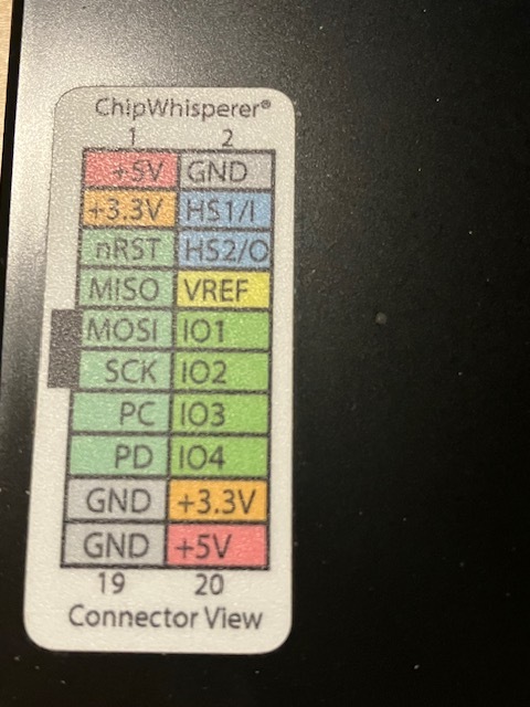
We include these stickers showing the 20-pin connector definitions with our ChipWhisperers (maybe you didn’t get one?)
IO1-4 are general-purpose IOs, usually used for UART and triggering; HS1-2 are used for clocks. scope.io will tell you what each is set to; scope.trigger will tell you which is the trigger.
Thanks for your reply that’s really helpful! Yeah unfortunately when I received the device from my advisor I do not have this pin map with my device. I also wonder how do I read this. Does the first column first row +5V correspond to my pin map I drew above first row first column [0][0] position and I read it vertically?
In addition I am currently at ScA lab 2 password checking tutorial. I wonder which lab gives me the detail of this internal mechanic so I can view that for information
It corresponds to this view, i.e. ground on top right and bottom left of picture.
There is no single lab which teaches you everything about CW. Instead, each lab teaches you a little bit about how to use CW and a little bit about side-channel attacks at the same time. If you work your way through everything, then you’ll get the complete picture.
For the rest there’s the documentation here and here.
It’s me again I am at the last step for connecting the CW to a custom device. Before I do that I want to make sure that I do not burn my other device down. So I have two questions:
On my custom target, I have two jumpers that can be used to measure power including some current changes or voltage drops or so. I am unable to upload a picture here so I will just describe that: The two jumpers are just two metal things looks like this from above.
X X
The “X” on the left is for Ground (GND) and the “X” on the right is for input (VDD). I assume that the CW gives the device a constant voltage input and measure some changes as the target is operating.
On the CW which is a ATMEL SPARTAN-6 CWLITE with a separate victim of XMEGA there is a measure port. The measure port has however 3 pins looks like this layout (looking from above)
Measure OOO JP10 (on the side) Metal outputs
The “OOO” are just PCB solderable pins whereas JP10 is a note on the right most pin. I yet to know which pin outputs power and which pin connects to ground. Also I wonder what the third pin is doing.
I wonder if anyone can help me out on these pins’ functionality and possibly some ideas for jumper connection. I know there’s no picture here cuz it’s not allowed for me to upload one. So hopefully the description is clear enough, maybe.
Also a final thing to add: can I control the measure’s output voltage. I need to control it below or equal to 3.3 voltes otherwise my board may be burned,
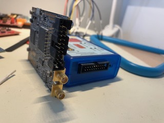
It sounds like you have a CW-lite with the target board attached (i.e. looks like the first picture here).
If you want to use a different target, then you’ll have to break apart your CW’s target, as explained here.
The measure port is usually connected to the low-side of the shunt resistor and ground – you can sort out which pin is which with a multimeter or by looking at the schematic
CW-lite provides 3.3V to the target (see the sticker from my first answer). If your target requires different voltages you’ll have to provide them yourself. There is a pin labeled 5V, but it’s not connected to anything on the CW-lite. All this info, by the way, can be found at CW1173 ChipWhisperer-Lite - NewAE Hardware Product Documentation
Luckily my CW lite is not attached with target, it’s a two pieces thing. Well the documentation is good then. I will check it out. Is this documentation the same for the 2-part CWLITE?
I used a multimeter to test on CW’s Measure ports. It seems like that the two ports (center one and the lower one that is close to the lower edge of the CW, next to C67, 68, 69) outputs a 0.5 V when the CW is idling. I assume those two are the ones that I connect to the jumpers.
The issue is that a 0.5V is relatively weird. I assume that CW only outputs 3.3V when it is detecting, is that correct though?
The measure port is an input to an ADC. I had meant to use a multimeter to see which pins are ground (the two outside pins of the SMA connector). Not sure what your jumpers are since I don’t have your target. Study the CW-lite schematic to sort out how to connect your target. For example here on page 9, you can see that for our xmega target, we connect the measure port to ground and to the low (right) side of the shunt resistor (R66).
Ah! I see what’s going on. Yeah I think I know what happened now. Thanks for the response and the data sheet those are really helpful. I was trying to look for them for a while.
I identified the trigger using scope.trigger and scope.io. The IO 4 is the trigger but when I try to trigger the thing, for some reason the CW lite says that it does not recognize a trigger. (I applied 0-3.3V rising edge to the IO4 port and test if the trigger is recognized). Then I applied it again and still nothing happened. The message I get as follows:
(ChipWhisperer Scope WARNING|File _OpenADCInterface.py:642) Timeout in OpenADC capture(), no trigger seen! Trigger forced, data is invalid. Status: 0f
(ChipWhisperer Scope WARNING|File _OpenADCInterface.py:642) Timeout in OpenADC capture(), no trigger seen! Trigger forced, data is invalid. Status: 0e
Typically, this timeout happens when the target is not actually issuing a trigger. Additionally, the scope must be armed in order for it to get successfully triggered.
Got it. Yes I am calling the function. I wonder it may be the issue of set up triggering. I am using a customized trigger on a customized target board (TI Tiva C board). I wonder in order for the CW to detect the trigger the trigger must be at a rising edge right?
In addition the target runs a clock of 16 MHz. Is the fast clock speed an issue of trigger failure? I double checked the GPIO output and it’s working as the LED lights up.
Like the XMEGA target, I also reset the trigger each time by put 0V on gpio. So it should work tho, but it’s not. Kinda frustrating.
This is controlled via the scope.adc.basic_mode property.
The target clock speed isn’t an issue, unless the trigger pulse is so narrow that CW might miss it. CW uses scope.clock.adc_freq to sample the trigger input line.
Yes the trigger is 3.3V. I made sure everything is to default so the basic_mode will be in its default value.
I figured out the issue. I made a mistake in constructing my own trigger high/low function. When turning GPIO port pin to low, I did OR operation rather than AND (which makes it stay at 1). A small mistake ruined everything.