CW1200 and ChipShouter glitch trigger setup problem

Hello,

I want to glitch a specific target using the ChipShouter in combination with the CW1200. I’ve the following setup in mind:

+---------------+                   +---------------+                     +----------------+
|               | Trigger       IO4 |               | AUX?           TrgIn|                |
|   Target      |                   |   CW1200      |                     |    ChipShouter |
|               +------------------>+               | +-----------------> |                |
|               |                   |               |                     |                |
+-------+-------+                   +---------------+                     +---------+------+
        ^                                                                           |
        |                                                                           |
        |                                                                           |
        |                                                                           |
        +---------------------------------------------------------------------------+

                                      EM-Glitch

The target generates a trigger signal. After that trigger, the CW1200 has to generate a precise delay for this signal, and trigger the ChipShouter after that delay.
I couldn’t make this setup work by using the Crowbar GlitchOut of the CW1200 as Trigger for the CS.
If I look at the Trigger Routing Screen of the CW1200, it looks like it’s possible to route the glitch out signal to AUX.
How can this be done in the software?

Or is there a different, better way to generate the trigger signal for the ChipShouter by the CW1200?

Thanks for you help,
Nils

Hello,

The crowbar glitchout “should” work - actually that is what I’m using as a triggering method for 80% of my ChipSHOUTER usage! So could troubleshoot that… although due to the MOSFET in the way with the crowbar it doesn’t go as narrow (or requires some effort in mapping commanded glitch width --> actual width). I assume that is the problem you are seeing (and not that it doesn’t work at all). If you aren’t getting it to work at all let me know, as it should work ‘fairly’ well.

As a quick work-around - are you using the CLKOUT (HS2) right now? You can definitely route a glitch out to that, and if you’ve got a CW1200 it should have come with the breakout board that has the SMA on the HS2. That should “cleanly” connect through as you want…

But on the aux signal - I’ll double check. I know we had some issue w/ the FPGA build, so I think it was removed (I see some of the SMAUX logic commented out - the FPGA code is all in the git repo). The FPGA tools tend to not like when we route these clocks all over the place with muxes. We may end up just needing to offer multiple bitstreams you switch between when you want to use different features, which have more fixed clock routing. This actually isn’t too bad to do, as the bitstreams get reloaded on connect anyway. And I think 99% of the time you’re using the SMAAUX for a specific use given your setup - that is there isn’t a need to switch half-way through your analysis for SMAAUX being the glitch out to SMAUX being the clock input for example.

Thanks,

-Colin

Hi Colin, thank you very much for your answer. We could resolve our problems in the meantime. We were able to use the glitch out on cw1200. We reversed your youtube video about Bam Bam for that :wink: so we could find the proper output settings.

Thanks a lot.

Nils

Hello,

I would like to ask this question here since it is similar to this topic.
I’m trying to do EMFI with the following configuration, which is very similar to Nils’ one.

+---------------+                   +---------------+                     +----------------+
|               | Power     Measure |               | Crowbar        TrgIn|                |
|  XMEGA Target |               CH1 |   CW1200      | Glitch              |    ChipShouter |
|  CW308        +------------------>+               | +-----------------> |                |
|               |                   |               | +----+              |                |
+-------+-------+                   +---------------+      | Aux out      +---------+------+
        ^                                                  |                        |
        |                                                  v                        |
        |                                            oscilloscope                   |
        |                                                                           |
        +---------------------------------------------------------------------------+

                                      EM-Glitch

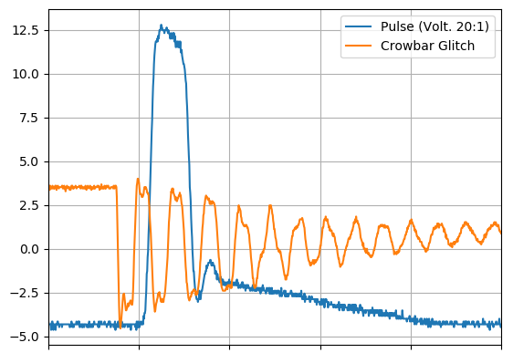
However, the output of Crowbar Glitch is only about ±1V, which is not enough for TrgIn of ChipSHOUTER.
Even after performing with the parameters referring to the Colin’s video here (e.g., glitch parameters such as width, offset and output), the output of Crowbar Glitch did not reach 3.3V.

Here are my first settings of CW1200.

fw_version = 
    major = 1
    minor = 23
    debug = 0
gain = 
    mode = high
    gain = 30
    db   = 24.8359375
adc = 
    state          = False
    basic_mode     = rising_edge
    timeout        = 2
    offset         = 0
    presamples     = 0
    samples        = 1000
    decimate       = 1
    trig_count     = 1
    fifo_fill_mode = normal
    stream_mode    = False
clock = 
    adc_src       = clkgen_x1
    adc_phase     = 0
    adc_freq      = 7384609
    adc_rate      = 7384609.0
    adc_locked    = True
    freq_ctr      = 0
    freq_ctr_src  = extclk
    clkgen_src    = system
    extclk_freq   = 10000000
    clkgen_mul    = 2
    clkgen_div    = 26
    clkgen_freq   = 7384615.384615385
    clkgen_locked = True
trigger = 
    triggers = tio4
    module   = SAD
    aux_out  = True
io = 
    tio1       = serial_rx
    tio2       = serial_tx
    tio3       = high_z
    tio4       = high_z
    pdid       = high_z
    pdic       = high_z
    nrst       = high_z
    glitch_hp  = True
    glitch_lp  = False
    extclk_src = hs1
    hs2        = clkgen
    target_pwr = True
    tio_states = (1, 1, 0, 0)
glitch = 
    clk_src     = clkgen
    width       = 48.046875
    width_fine  = 0
    offset      = -44.921875
    offset_fine = 0
    trigger_src = ext_continuous
    arm_timing  = after_scope
    ext_offset  = 1
    repeat      = 1
    output      = glitch_only
SAD = 
    threshold = 3000
    reference = [551. 494. 385. 449. 522. 408. 560. 566. 664. 689. 705. 688. 685. 692.
 686. 680. 681. 682. 688. 587. 661. 526. 614. 608. 657. 660. 665. 649.
 653. 652. 653. 651. 652. 649. 656. 552. 635. 512. 580. 571. 619. 628.
 641. 619. 624. 628. 635. 625. 625. 623. 624. 522. 601. 482. 559. 559.
 603. 607. 620. 605. 609. 607. 609. 598. 605. 599. 613. 501. 590. 473.
 545. 543. 585. 595. 597. 582. 584. 587. 597. 587. 596. 589. 602. 500.
 567. 442. 516. 521. 566. 581. 588. 580. 580. 584. 586. 576. 586. 574.
 584. 477. 560. 434. 520. 517. 557. 572. 579. 560. 559. 571. 570. 568.
 570. 564. 581. 472. 557. 429. 512. 509. 558. 566. 566. 558. 559. 566.
 569. 566.]
decode_IO = 
    trigger_pattern = None
    rx_baud         = 38360.23667279412
    decode_type     = USART

Regards,
Shoei

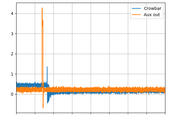
The following graph shows the observed voltages of the aux output and the crowbar output on an oscilloscope. As this figure shows, the crowbar output does not reach 3.3V and cannot be used as a trigger input.

AuxOUTandCrowbarGlitch

Regards,
Shoei

Hi Shoei,

I’m fairly sure there’s something wrong on the ChipShouter end here as the glitch port is open drain. Do you have the ChipShouter set to an active low trigger?

Alex

Hello Alex,

Thank you for your kind reply. I have not set the chipSHOUTER to an active low trigger.
The graph in my recent post is based on direct observation of the output of Aux and Corwbar Glitch with an oscilloscope. Therefore, I was wondering if there is something wrong with the ChipWhisperer. Is it possible that the output of the Crowbar Glitch does not reach 3.3V according to the specifications?

Here are settings of ChipSHOUTER.

api_version = 0.0.0
armed = False
voltage =
set = 500
measured = 21
pulse =
width = 160
repeat = 1
deadtime = 10
actual width = 160
state = disarmed
trigger_safe = False
faults_current =
faults_latched = [‘fault_trigger_error’]
temperature_mosfet = 29
temperature_diode = 27
temperature_xformer = 30
arm_timeout = 2
hwtrig_term = True # 50 orm (connected by sma-smb cable)
hwtrig_mode = True # Active-high
emode = True # firmware trigger mode
mute = True
absent_temp = 1
pat_enable = False
pat_wave =
reset_config = 0
reset = False
board_id = *********
boot_enable = 0

Thanks,
Shoei

I ran ChipSHOUTER and chipWhisperer with every combination (including an active low trigger for ChipSHOUTER) of the following parameters, but it did not work.

hwtrig_mode = [True, False]
hwtrig_term = [True, False]
output = [“enable_only”, “glitch_only”]
trigger_src = [“ext_continous”, “ext_single”]
glitch_hp = [True, False]
glitch_lp = [True, False]

Here are some examples.

trig_mode: True, trig_term: True, output: enable_only, trig: ext_continuous, HP: True, LP: False
→ Nothing will happen.
trig_mode: False, trig_term: False, output: enable_only, trig: ext_continuous, HP: True, LP: False
→ ChipSHOUTER’s fault LED lights up with the error of ‘fault_trigger_glitch’.

Thanks,
Shoei

Hi Shoei,

As said earlier, the ChipWhisperer glitch port is an open drain configuration, meaning it can only connect something to ground, not provide power to it. The active low configuration on the ChipShouter enables a pull up resistor, which will be pulled low by the ChipWhisperer when the glitch is active.

Try disconnecting the ChipWhisperer from the ChipShouter and set the ChipShouter trigger input to active low, high impedance. If you’re getting a fault, then there is an issue with the ChipShouter setup. Otherwise, I’d say there’s an issue with the ChipWhisperer setup.

Alex

Hello Alex,

Thank you very much for the instructions, I now understand the principle of Crowbar glitching.

Try disconnecting the ChipWhisperer from the ChipShouter and set the ChipShouter trigger input to active low, high impedance.

The fault LED did not light up either with the ChipSHOUTER alone or with the ChipWhisperer connected. So I have confirmed that the problem is in the ChipWhisperer setup.

I understand that the key parameters are the following, but are there any other parameters I should consider?

cs.emode = True # firmware trigger mode (cs: ChipSHOUTER)
cs.hwtrig_mode = False # Active-low
cs.hwtrig_term = False # High-impedance
scope.glitch.output = “enable_only”
scope.glitch.clk_src = “clkgen”
scope.io.glitch_hp = False
scope.io.glitch_lp = True
scope.glitch.repeat = 20 # should be chaged

Thanks,
Shoei

1 Like

I was able to confirm that it works well.

When I pressed the Pulse button on the ChipSHOUTER, the Pulse LED lit up, so I mistakenly thought it would also light up when driven by an external trigger. The voltage monitor of the ChipSHOUTER showed that the pulse was emitting.

Thank you very much for your time, Alex!!

pulse2

1 Like