Hello guys, I’m attempting to voltage glitch an STM8L target on a custom UFO308 board.
I’m supplying power and a 16MHz clock to the target from the CW, the target is using a 8x divider and running at 2MHz. I’m using a GPIO pin from the board to trigger the injection of a voltage glitch.
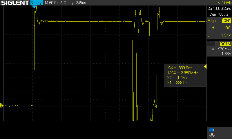
However I’m running into an issue, the glitch is delayed by about ~340ns from the trigger. I have no idea why this is happening, shouldn’t the injection delay with offset=1 and ext_offset=0 be in the order of a few nanoseconds?
There is some delay due to the glitch logic - it’s a number of cycles of the “glitch clock”. So at 16 MHz clkgen (which becomes the glitch clock) you have 62.5 nS cycle = ~5-6 cycle delay from your measurement (which I think jives with trigger logic design).
The quick solution is to run clkgen faster. Note that the glitch logic can run faster than the ADC (which is limited to ~100mhz). So an easy solution with some external hardware is:
Plug a 16 MHz XTAL into the UFO baseboard.
You can route this signal to both the target device & to the CLKIN pin (HS1).
Configure clkgen to use extclock & set to a higher frequency:
scope.clock.clkgen_src = “extclk”
scope.clock.extclk_freq = 16E6
scope.clock.clkgen_freq = 128E6
scope.clock.reset_dcms()
scope.glitch.resetDcms() #Old function API, but useful when you change freq like this
Note setting extclk_freq just allows it to auto-calculate the correct mul/div for clkgen when not using the internal timebase.
The normal ChipWhisperer builds don’t have dividers in the frequency output, so you can’t output a lower frequency than CLKGEN. This means if you’ve already got a 16 Mhz xtal the above should work great.
Watch out for the glitch.width now though - it might be too narrow to actually generate an output. The solution may be to use either a higher repeat number, or to switch to enable_only output glitch mode.
Thanks for the suggestions Colin, I’ll try them out. It’s understandable that there would be a delay I thought it might’ve been normal at first but I just assumed since internally the ChipWhisperer is using an FPGA that the triggering would be synchronous or almost. Shows how little I know…
I was initially driving the target with it’s internal clock and using a much higher clkgen frequency. I tried to supply the target’s clock with the hope of getting more repeatable timing, I guess I’ll return to that approach.
Speaking of which, I’m having trouble having the target produce any successful faults at all, even with over 300 000 various attempts using different offsets and glitch widths.
I’m getting to the point where the target stays functional around 60% of the time and the rest crashes without triggering it’s internal reset mechanisms. I determined the type of reset by examining it’s output voltage, which would steadily drop over a relatively long period of time, unlike a reset from a glitch that’s too strong which just shuts down the target immediately. Do you believe my intuition of these two different ‘types’ of resets is correct?
I feel I’m a bit lost as I’ve made virtually zero progress. Do you think I’m on the right track? Do you have any other advice?
Thanks a ton for your support, it’s really appreciated.
Not sure on the exact target - but our standard process (even when targetting bootloader etc) is to start with the double-loop code:
int cnt = 0;
while(1){
volatile int k = 0;
for(volatile int i = 0; i < 1000; i++){
  for(volatile int j=0; j < 1000; j++){
    k++;
  }
 }
 printf("%d %d %d %d\n", i, j, k, cnt++);
}
You can adjust that as needed for targets - in particular the value of 1000 is just something so it spits out a result every ~0.5 to 1 seconds. For older devices you might hack in some more basic print code.
The while(1) loop doesn’t require a nice trigger, and just “mess around” until we see something. Where messing around involves:
Changing pulse widths.
Changing cables (SMA cables can affect this a lot - if you dont’ have different lengths even try just jumper wires).
Changing the power supply setting - this is easy on the UFO board since you can use the variable VCC option. Sometimes lower voltages are more helpful.
Switching between ‘HP’ glitch and ‘LP’ glitch (they have slightly different characteristics - for the most part one doesn’t end up being ‘better’ than the other).
Changing the clock frequency - often running the device as fast as possible can be helpful too, since the timing slack is much lower now.
Normally if you’re seeing occasional resets it’s a good starting point! But this removes the offset problem from the code.
Thanks for the tips, I tried implementing the double loop. I have a few doubts about the process:
Do you try a single glitch per loop or multiple ones generally?
In your experience, on average with glitch parameters that might result in success, how often will the target reset itself? 10%, 30%, 90% of the time? Just a ballpark figure of course. I understand this can be highly variable
With correct parameters how often will you see the loop skip? Is it still a 0.1% chance or more like 10%?
In the ufo boards you have design there is generally at least a 100nf bypass cap, I replicated this design, is this component helpful for voltage glitching or should I remove it?
Does the value of the shunt resistor impact the voltage glitching at all?
Thanks again man, your tools and advice are making this process much easier for me. I’d be totally lost otherwise.