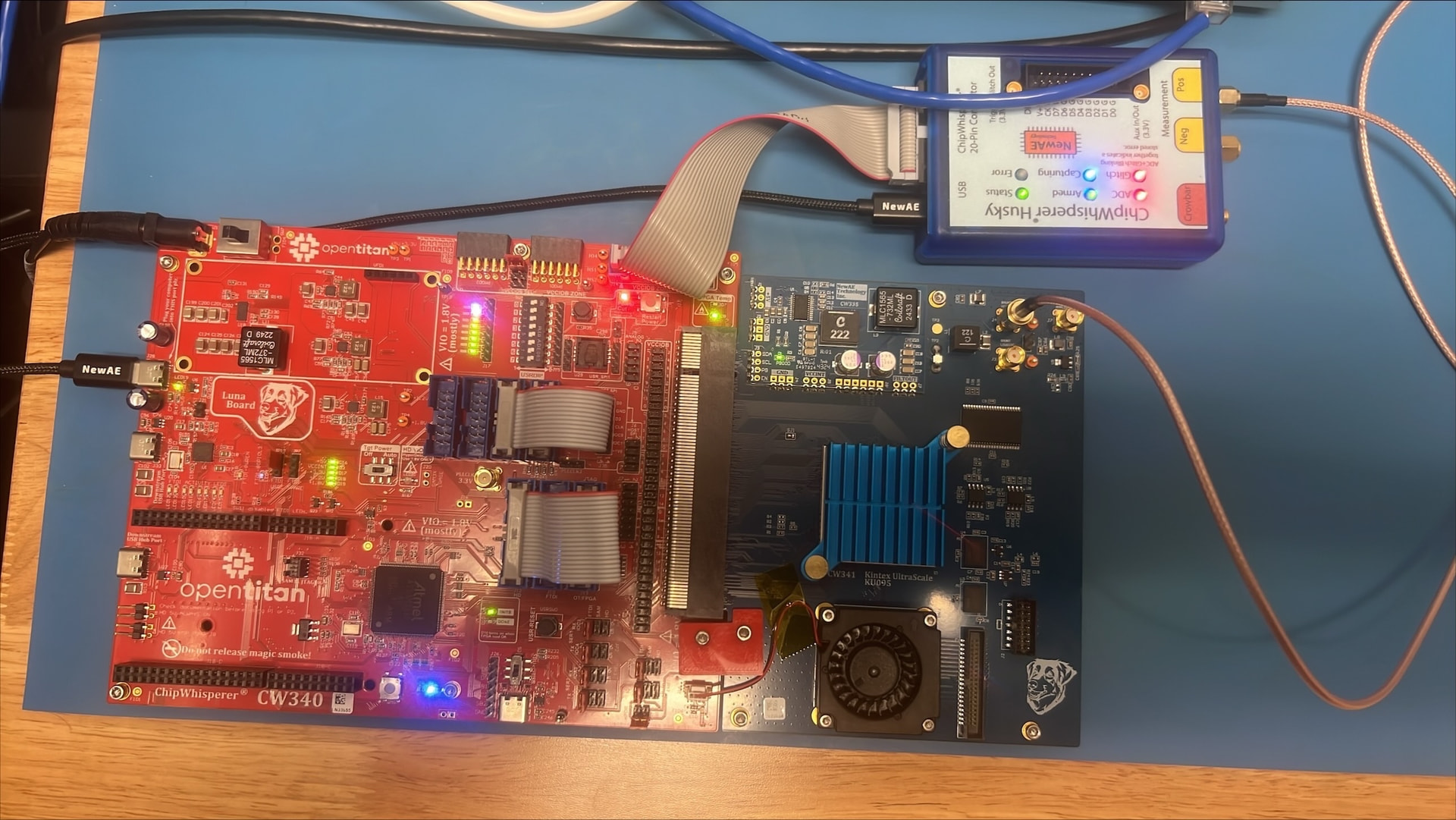
I am testing out a new CW340 (specifically the 340-OT kit) with the Husky. The hardware tests pass, but I cannot recover the AES key following CW340_AES_test.ipynb with the supplied AES bitstream (even with >100k traces). I found this forum post that suggests the issue might be some decoupling capacitors that need removed? These capacitors are indeed present on the board. What is the best way to address this issue?
We have had the decoupling capacitors removed, but I am still unable to recover the AES key following CW340_AES_test.ipynb.
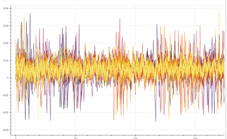
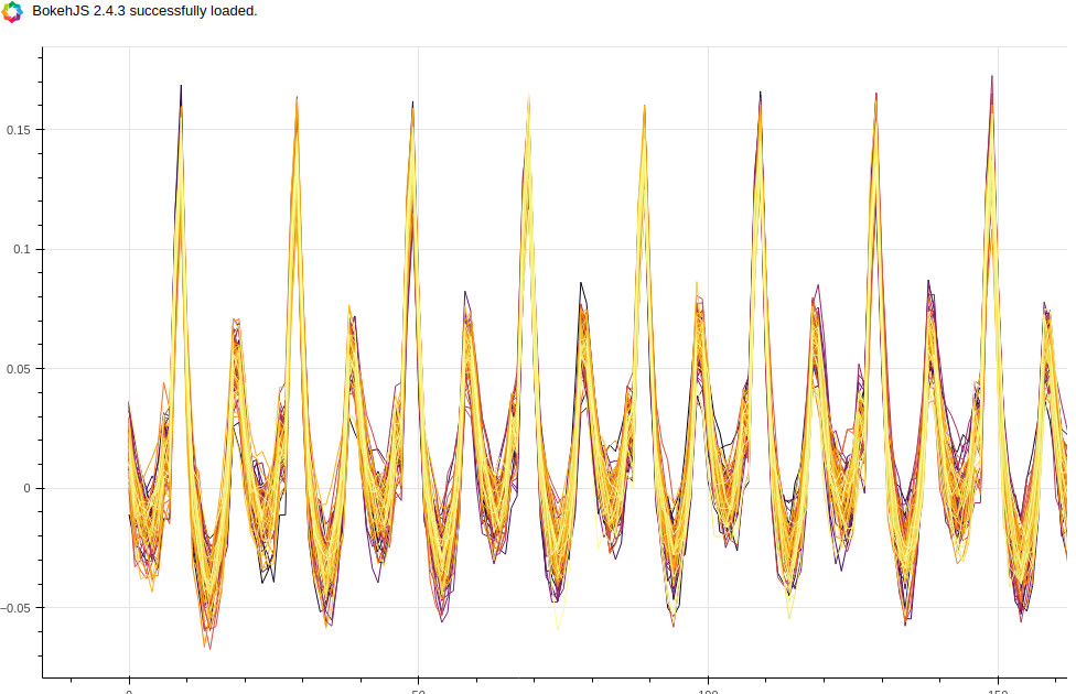
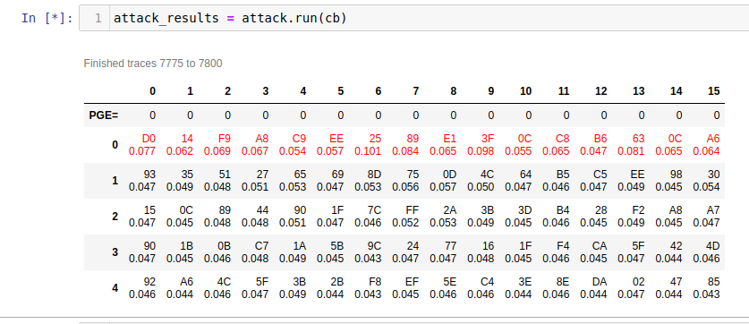
Here are some of the traces captured during the test:
The average APG is 124. None of the correct key-bytes are guessed correctly, nor are they even within the top 5 guesses.
print(scope.errors) returns
sam_errors = serial rx overflow
sam_led_setting = default
XADC errors = False
ADC errors = False
extclk error = False
trace errors =False
scope.clock returns
clkgen_src = system
clkgen_freq = 7370129.870112987
adc_mul = 4
adc_freq = 29480519.48051948
freq_ctr = 10000465
freq_ctr_src = extclk
clkgen_locked = True
adc_phase = 0
extclk_monitor_enabled = False
extclk_error = False
extclk_tolerance = 102.996826171875
The jumpers are placed correctly
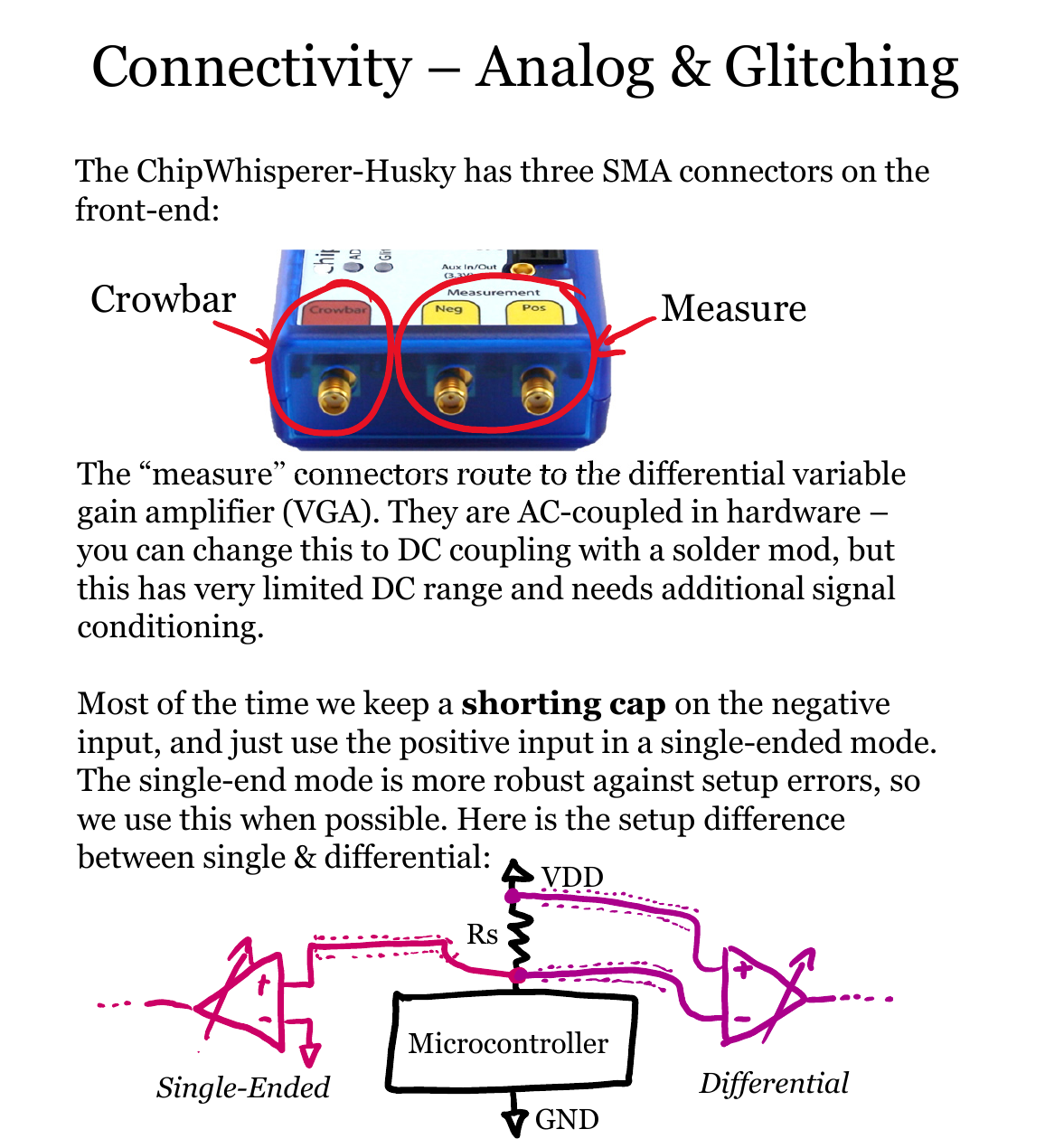
The SMA cable is attached from Husky POS to SHUNT HIGH on the target board. The SHUNT LOW is left open. Is this correct? Or should Husky NEG be attached to SHUNT LOW as well?
You reference CW340_AES_test.ipynb, which sets (among other things) scope.clock.clkgen_src = 'extclk', yet the output above shows that you have clkgen_src set to “system” instead.
This is a problem because the FPGA target is set up to use a clock generated by the CW340 PLL. This clock is provided back to Husky so that it may sample synchronously with the target’s clock (that’s what clkgen_src = ‘extclk’ does). Here instead you have Husky set up to generate an ADC sampling clock that has no relation to the target clock. This explains why your traces don’t look so great.