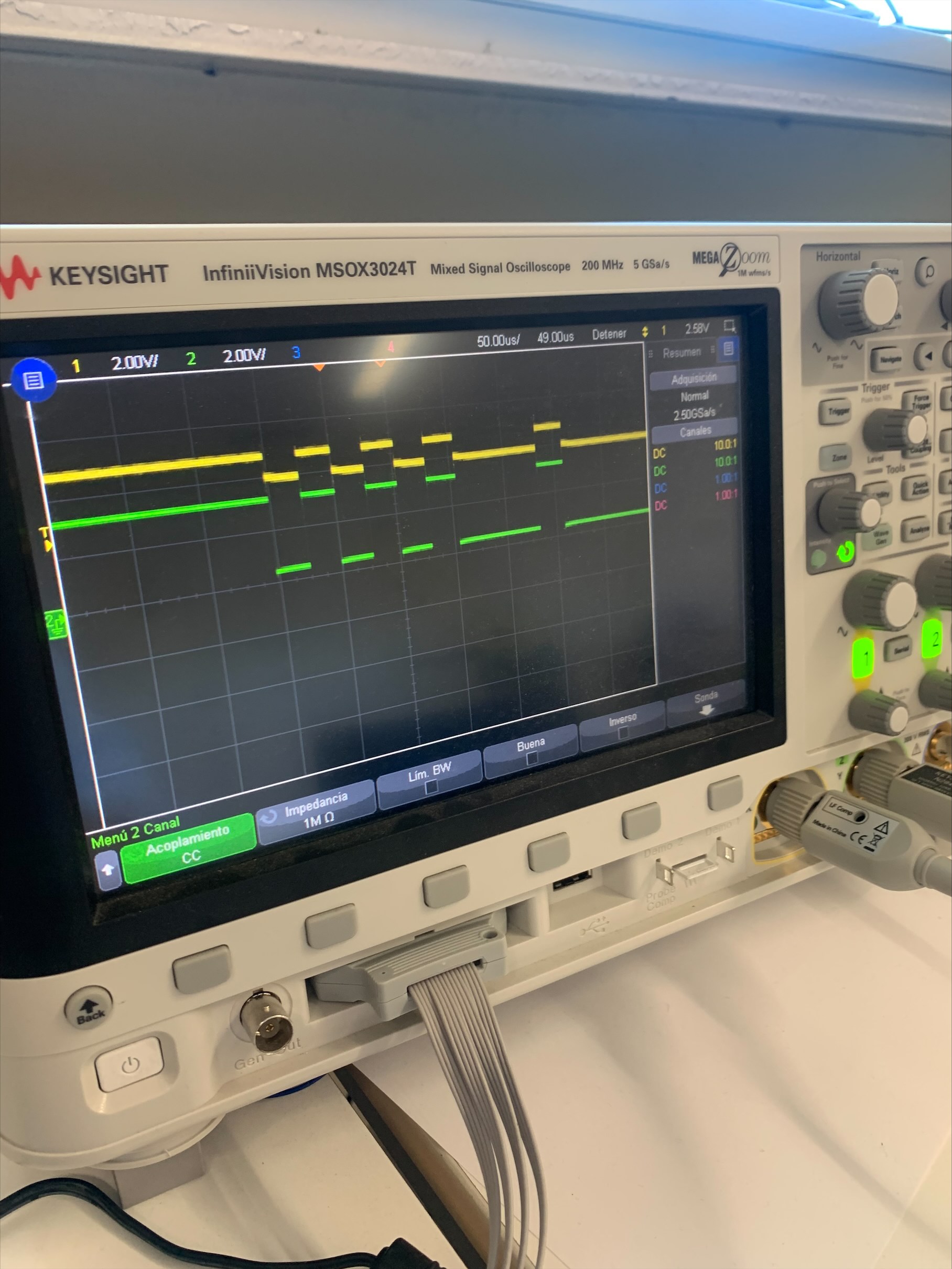
We are using CW506 Advanced Breakout board to level shift the signals between the CW-lite (3.3V) and Arduino (5V). However, there is a problem in the board when the signal on the CW side is 0V, it gets shifted to 4V on the Arduino side (see pic attached).
Thanks for doing some debugging on this. If you measure VCC-IO (TP11), do you get 5V there? Also, what switch settings do you have and what connections have you made between the Arduino and the 20-pin connector on the CW506?
Hi Alex,
You are right, we had the settings for VCC-IO set to 3.3V. However, now that we switched to VREF (that we route from 5V pin of Arduino), we are no longer able to program the Arduino from the CW-Lite (by using the command cw.program_target(scope, program, aes_hex_path)).
When trying to program it, we get the following error:
OSError: Verify failed at 0x0000, c != ff
Our connections are the following:
Arduino CW506 20-pin connector
Rx (0) 12 (Rx - IO1)
Tx (1) 10 (Tx - IO2)
TRG (A0) 16 (TRG - IO4)
5V 8 (VREF)
GND 2 (GND)
At the moment we are not connecting the Arduino clock (pin 8 on Arduino) to pin 11 (HS1) on CW506 as we saw that introduces a lot of noise and is not necessary for establishing the SimpleSerial protocol between the CW and Arduino. We want to get this protocol running first, and then proceed to capture the traces and perform an attack.
Any thoughts?
Yeah, we do. It seems that there is some large capacitance somewhere, cause we’ve taken a look at the Tx line and the signal has a small slope (takes a long time to reach the final level and it actually never reaches ground).
Hmm, I do see an issue that came up a few years ago about the GPIO3/GPIO4 pins not being driven properly. From its datasheet, it looks like the GTL2003 requires pull up transistors on the target side pins when VCCIO > 3.3V (https://www.nxp.com/docs/en/data-sheet/GTL2003.pdf). Can you try connecting a pull up resistor from MOSI to VCCIO (seems like 330 ohm worked in the past) and see if that fixes things for you?
We’ve tried your suggestion and put the 330 Ohm resistance between MOSI and VCCIO. We still weren’t able to program Arduino, so we switched to 3.3V again and programmed it (with the pull-up resistance). Then we changed VCCIO from 3.3V to 5V, disconnected AVR ISP and ran the command:
target.send_cmd(‘p’, 0x80, data)
and the levels on the TX line now seem fine and are between 0V and 5V. Still, Arduino stays stuck in the same loop as before, waiting for a character to arrive. We double checked the baudrate and it is 38400. Is it possible that there is something wrong in uart.c code?
Probably the best way to check that UART is working is to follow my previous suggestion and print a debug message on startup - this will make sure that the baud rate on the Arduino side is as expected.
Additionally, our Notduino target typically runs off an external 7.37MHz clock. If you haven’t messed with any of the clocks, your Arduino is probably running at a different frequency than expected so the baud rate will be different.