Hello there,
I’m currently experimenting with capturing power traces.
While doing so I called print(scope) to see my current config.
After doing so the D7 LED on the CWLite turns on and doesn’t turn off again.
Everything seems to work but I couldn’t find any informationen about why the LED is on.
The output of print(scope) is the following (I removed sn from the output)
cwlite Device
fw_version =
    major = 0
    minor = 64
    debug = 0
gain =
    mode = low
    gain = 0
    db   = 5.5
adc =
    state          = True
    basic_mode     = rising_edge
    timeout        = 2
    offset         = 0
    presamples     = 0
    samples        = 24400
    decimate       = 1
    trig_count     = 2368565036
    fifo_fill_mode = normal
clock =
    adc_src       = clkgen_x1
    adc_phase     = 0
    adc_freq      = 96000000
    adc_rate      = 96000000.0
    adc_locked    = True
    freq_ctr      = 0
    freq_ctr_src  = extclk
    clkgen_src    = system
    extclk_freq   = 10000000
    clkgen_mul    = 2
    clkgen_div    = 1
    clkgen_freq   = 192000000.0
    clkgen_locked = True
trigger =
    triggers = tio4
    module   = basic
io =
    tio1         = serial_tx
    tio2         = serial_rx
    tio3         = high_z
    tio4         = high_z
    pdid         = high_z
    pdic         = high_z
    nrst         = high_z
    glitch_hp    = False
    glitch_lp    = False
    extclk_src   = hs1
    hs2          = None
    target_pwr   = True
    tio_states   = (1, 0, 0, 1)
    cdc_settings = bytearray(b'\x01\x00\x00\x00')
glitch =
    clk_src     = target
    width       = 10.15625
    width_fine  = 0
    offset      = 10.15625
    offset_fine = 0
    trigger_src = manual
    arm_timing  = after_scope
    ext_offset  = 0
    repeat      = 1
    output      = clock_xor
And a short different question: adc_freq is set to 96000000 by default and my target has a freq of 64 MHz. Should I change the value of adc_freq to 64000000 for better trace results?
D7 means that the ADC clock is not locked. (The picture at the top here defines all the LEDs). Your print(scope) doesn’t show any problems; if you share the notebook which led to this condition, I can help pinpoint why.
ChipWhisperer is meant to be use synchronous sampling. This doesn’t mean using the same frequency as the target clock; it means deriving the sampling clock from the actual target clock. How to set scope.clock depends on whether ChipWhisperer is supplying the target its clock, or vice-versa. If you explain your target’s clocking arrangement I’ll be able to help you better.
My target has an internal clock. I modified my notebook a little since posting but here is the code:
import chipwhisperer as cw
import serial
import time
from tqdm.notebook import trange
from os import urandom
scope = cw.scope(scope_type=cw.scopes.OpenADC)

serial_settings = {
    "port": "COM5",
    "baudrate": 115200,
    "parity": serial.PARITY_EVEN,
    "stopbits": 1,
    "bytesize": 8,
    "timeout": 5
}

# capture setup
scope.default_setup()
# set trigger
assert scope.trigger.module == "basic", "CW-Lite only supports module 'basic'"
scope.trigger.triggers = "tio4" # FPGA-TARG4 Trigger Input

# capture settings
scope.adc.basic_mode = "rising_edge"
scope.adc.samples = 24_400
scope.adc.offset = 1_500
scope.io.tio4 = "high_z"

# testing capture
test_trace_array = []
test_key_array = []
iv = bytearray([0x00])
key = bytearray([0x00])
N = 5
command = key
with serial.Serial(**serial_settings) as ser:
    for i in trange(N, desc="Capturing traces"):
        scope.arm()
        ser.write(command)
        ret = scope.capture()
        if ret:
            print("Target timed out")
            continue
        test_trace_array.append(scope.get_last_trace())
        test_key_array.append(key)
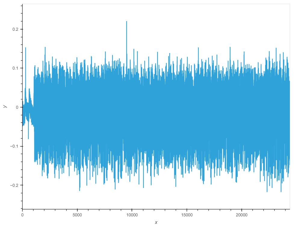
The trigger pin tio4 is connected to RX of the target so ser.write() triggers the capture.
This is one of the traces:
The important question is whether you can provide the target’s clock to ChipWhisperer. If so, put it on the HS1 pin, and use:
scope.clock.adc_src = "extclk_x1"
scope.clock.reset_adc()
time.sleep(1)
assert scope.clock.adc_locked
If not, then CW is not the best tool for the job- as I said above, CW is meant to sample synchronously, and that requires access to the target clock. This is where a high-speed oscilloscope would work best. But you can try:
scope.clock.adc_src = 'clkgen_x1'
scope.clock.clkgen_freq = 64e6 # or 105e6, see which works better for you
scope.clock.reset_adc()
time.sleep(1)
assert scope.clock.adc_locked
In this case, do not expect scope.adc.trig_count to be constant.
Sadly I can’t provide the device clock.
And maybe some context for what I want to do.
Currently I try to execute a DPA attack with the traces I collect. I wanted to use trig_count to somewhat influence when the capture starts to have sync traces (the uart trigger isn’t the best).
I’m currently trying to work with ResyncSAD but with no success.
import chipwhisperer.analyzer as cwa

# sync traces
resync_traces = cwa.preprocessing.ResyncSAD(project)
resync_traces.ref_trace = 0
resync_traces.max_shift = 500 #?
resync_traces.target_window = (0, 2000) #?
resync_project = resync_traces.preprocess()
I loaded the traces in the project with
trace = cw.Trace(scope.get_last_trace(), "", "", key)
project.traces.append(trace)
I read in a different thread that there was preprocessing for spikes but I think it isn’t available in the current version. Well how do I have to set max_shift and taraget_window they seem to work together but how idk…
Thanks for your help until now