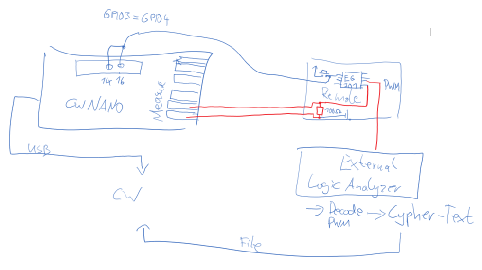
after I went through the tutorials, I broke of the integrated target in order to trace an external target: a remote control using a EG301 encoder, that seems to be a clone of the microchip HCS301.
With this I can trigger the target board to generate encrypted data (32 bits) and receive it on the PC. But I see two problems (see next post because of number of images limits)
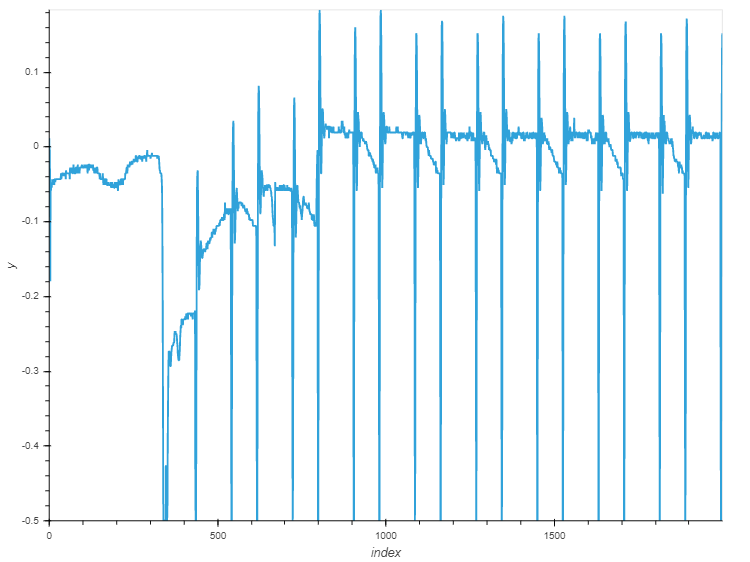
The shunt resistor in the integrated target was on the positive side. But my target runs at 5V, so I guess doing so will destroy the CWNANO’s amplifier stage. Is there a reason, why the shunt was placed on the positive side (VDD)? In the power trace using the gnd-shunt, I see strong spikes to the negative direction, maybe overshooting? Might be inverted?
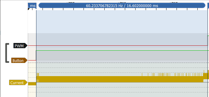
The duration after trigger until start of RF signal is around 16ms, so I expect to find correlations there.
But, this is too much for the sample buffer at lowest sample rate, so I’ like to use a trigger offset to skip to the last encryption round. Is there a technical reason, the CWNANO scope does not implement the trigger offset? It should be possible to skip some samples, so I have to recompile the CWNANO firmware, right? Or any other recommendation what I can do?
The CW-Lite and Pro models implement the trigger offset feature in the FPGA; the FPGA was omitted from the Nano for cost savings.
The front end amplifier has a 3.3V supply, so in addition to the possibility of damaging it, you won’t get nice measurements if you feed it signals in excess of that.
Can you adjust the shunt resistor so that the measurement signal stays within range? Otherwise maybe a voltage divider?
thanks for your comments. I had a look at the schematic, and it looks like the input is ac-coupled only. So sensing a vcc-shunt in a 5v circuit should be safe. But my question remains, is there a reason for placing the shunt on vcc instead of gnd?
The shunt is on Vcc because many targets have different Vcc pins for different parts of the chip (Vcore, IO, etc.) meaning you pick up less unwanted noise from stuff like I/O. If it’s just a simple Vcc/Gnd setup, there shouldn’t be much difference between the two.
Looking at your second picture, it definitely looks like the voltage is clipping on your target. Switching between Vcc and Gnd probably won’t solve your issue here. The Nano doesn’t have an adjustable gain on its amplifier, so your best bet is to follow JP’s advice and use a smaller shunt resistor.
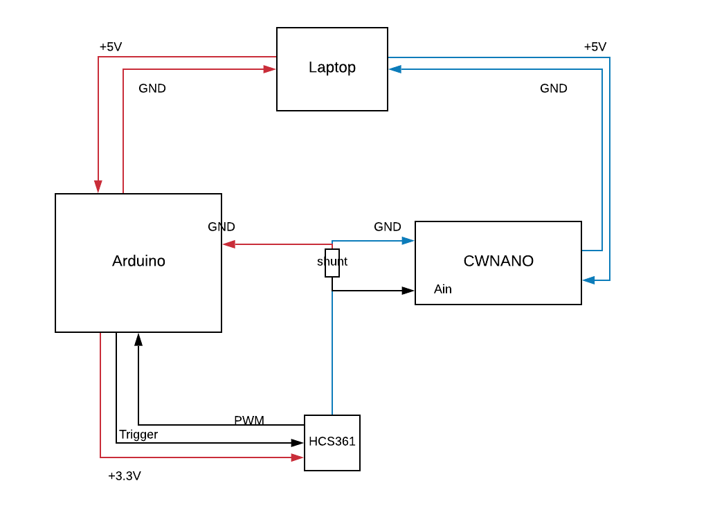
I know this post is old but I’m trying to do basically the same thing with the HCS361. I would like to, if possible, automatically send a button press on my remote to trigger both the encryption and trace capture. My current setup is as pictured:
which seems to be basically the same as the diagram in the original post. Forgive my ignorance but my question is if it’s okay that the ground path from the HCS361 is being split. My intuition tells me that this is wrong but I can’t come up with a reason why.
If it is wrong, is there a circuit where I can get the Arduino and CWNANO working in conjunction? I’d rather not have to reprogram the CWNANO but I realize that may be the easiest option.
the ground loop should not be a problem. I think it is more important to have the hcs and nano tightly coupled and short wires to the adc input to minimize noise. Good luck with capturing! Please share some graphs, when available.
Henning
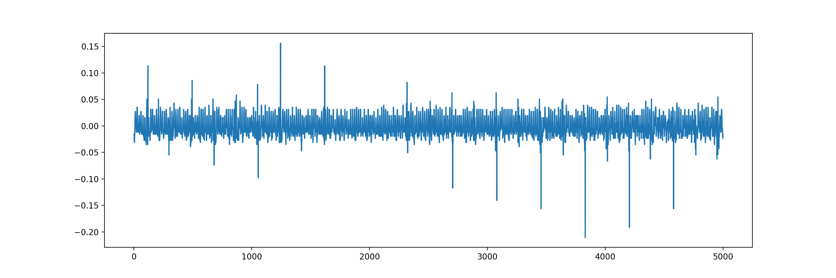
Here’s my first attempt. I think I’m on the right track. I know I need to increase the buffer size and refine when I’m triggering. Let me know if you have any ideas how to improve the trace as well.
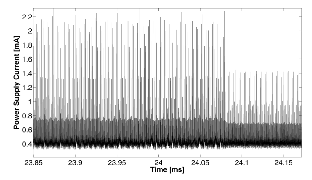
I’m using the default sample rate, which I think is 20Msps. I agree that it does look like noise but a sample plot from the Keeloq CPA paper looks maybe a little similar (keep in mind they are using a much higher sample rate):
You have to reduce noise and increase sample rate. Since you can not run in synchronous sampling, you don’t hit the power spikes. That’s why you have this random irregular pattern. The paper graph shows a repeated pattern.