Hi, I’d like to take the next step in understanding how to connect the chipwhisperer to another board. I have the level 2 kit.
So, I bought a random board that operates on 3.3 volts. It’s been programmed with the arduino client.
All I want to achieve is performing the captures and analysis of the power signals using the chipwhisperer. I don’t want to use the chipwhisperer to program the board etc.
Initially, I thought I could just use the Advanced Breakout Board (CW506) in the following way:
Connect chip whisperer 20-pin adapter to 20-in adapter on LEFT side of Advanced Breakout Board
Connect the small 6 pin grouping labelled “AVR/SPI” on right side of Advanced Breakout Board to the correct pins on the target (MISO to MOSI, etc, etc, etc)
I’m also assuming here that the Chipwhisperer powers the target through the “AVR/SPI” pin labelled VCCIO (?)
Then hit capture in the Chipwhisperer software. But I haven’t attempted this because I noticed that in the tutorials the chipwhisperer doesn’t seem to measure anything through the 20-pin adapter and uses a seperate measuring line. There is no “measure in” / “measure out” on the Advanced Breakout Board, so I don’t know what to do. Do I splice the VCCIO pin? do I do something else entirely?
Would anyone be so kind as to take a few minutes out to tell me (in absolute laymens terms) how to wire everything up (e.g. connect whipwhisperer header to Advanced Breakout Board; connect AVR/SPI pin #1 on advanced target board to pin xx on the adafruit board)? If it’s easier to use the UFO board then I do have that also, but that seems more difficult? I don’t know.
I know this sounds a lot like asking someone to do it for me, and I suppose I am in a way, but I’ve been banging my head against a wall for some time and I think (hope?) that if I can see one real world example with a truly external target that I have access to, perhaps then I can get a feel for why things are done the way that they are, and have something I can apply conceptually myself to other projects.
Thanks in advance to whoever pities this message enough to help out an absolute noob trying to learn about SCA.
Unfortunately there is no simple recipe for this sort of thing…here’s what you need to do, at a high level:
Since you don’t want to use CW to program your target, you don’t need many pins on the 20-pin connector. I’m assuming you’ve gone through the basic tutorials already (if not, take the time to do them, they will help you understand the basics).
Next you’ll have to define your objective. For example, do you want to replicate Tutorial B5 but with the Feather as the target? Then the next step would be to implement AES and the SimpleSerial protocol on the Feather.
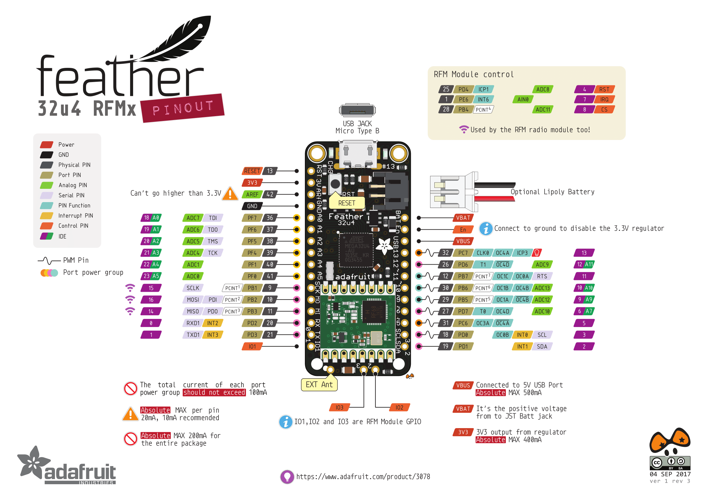
The Feather SW would need to accept SimpleSerial commands on a UART port (using IO1 and IO2 of the 20-pin, to follow convention), and provide a trigger back to CW (using IO4).
The second-last part is the clock: CW performs best when its clock is synchronized with the target. For that you have two options: either feed the CW clock to the Feather (using HS2/O) or feed the Feather clock to the CW (using HS1/I). I’m not familiar with the Feather so I don’t know what your options are for achieving either of these.
Finally, the power measurement, which as you point out doesn’t go through the 20-pin, but through the separate “measure” port. Non-CW targets don’t have a handy measure port so it’s up to you to create one. You’ll want to consider removing decoupling capacitors and somehow adding a shunt resistor in front of the processor’s Vcc input. Have a look at CW target boards to see how this is usually done.
The CW platform is quite flexible and so this is just one of many ways to do this, but if your objective is to replicate the existing tutorial on the Feather target, that’s what I would do.
Not the full answer you were looking for but hopefully enough to get you moving in the right direction?
Thanks for the response. You’re quite right, I’m trying to get Tutorial B5 to work on an abitrary board - in this case, the feather.
Ok, so IO1 and IO2 for serial communication (rx/tx).
IO4 for a trigger.
I need to work out some way of getting clock (either going in to target, or out from target), but if I’m really lucky and the stars somehow align, I might be able to get away without that if it’s not a possibility with the target device.
I need to add a VCC shunt resistor. Can this just be a normal resistor connected like this?
                                    ________________POWER TO THE REST OF THE DEVICE
                                    |
                                    |
                                    |           ________MEASURE PORT on chipwhisperer board (which hole?)
                                  A |           | B
             power from chipwhisperer--[Resistor]
I currently have the chipwhisperer powering the target device through it’s 3.3v and gnd pins.
The “using the measurement port” section on this page (https://wiki.newae.com/CW1173_ChipWhisperer-Lite#Using_Measure_Port) is empty. What do I connect the three holes to if I’m using regular breadboard jumper cables instead of an SMA adapter? Just the “B” side of the resistor in my image above connected to the middle pin (the pins on either side both seem to be ground, I assume I only need one connected to the target system’s ground)? If so, can the just be a random ground pin on the target device?
What size resistor should I use for the shunt in the ascii art? Does it matter what the resistance value is? Or do I just pick one at random?
Thanks for the help. I’m trying my best to follow / understand. It’s hard to know what to search for online without “knowing” what it is I don’t know (probably everything tbh).
Just a quick edit to add that the feather does have “XTAL1” / “XTAL2” but they are not brought up to a pin, and this chip is very tiny. Not sure if I can actually solder anything to these legs even if I manage to pry them up off the board somehow.
For the matter of the clock, once I know what I’m doing re: getting the rest of it running, I’m just going to hope somehow this works out with a clock to force or lock on to. and failing that I’ll have to look at micro-soldering them or something.
Still keen for help with the above if anyone has the time to help me by answering my (probably very silly, sorry) questions. Many thanks.
                    ______[resistor]__________Feather XMEGA Vcc input
                    |    |          |
                    |    |          |
                    |    |          |________MEASURE- PORT
                  A |    |
         powersupply     |___________________MEASURE+ PORT
The other option is an H-field probe, which eliminates the need for a shunt.
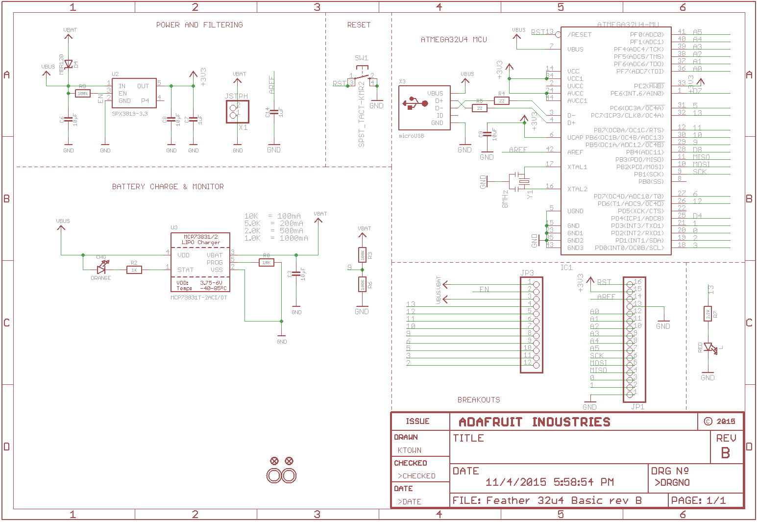
The Feather can be powered by the CW 20-pin 3.3V if the Feather’s current draw isn’t too high. This is how the basic CW-lite targets are powered.
The shunt resistor can’t be randomly chosen. Figure out the Feather’s current draw and apply V = I x R so that the voltage drop across the shunt doesn’t lower the target voltage too much.
You’ll get much better results if you manage to use a synchronous sampling clock; see the paper referenced here for details.
Finally, an idea: why not try this on an Arduino Uno instead, using the Notduino as a reference?
Thanks again for the response, the diagram, and the whitepaper link. So it sounds like I can measure off the power input pin or anywhere in that sort of area which is great - mostly I was trying to determine whether it can be between the powersupply and the rest of the device (this chip is tiny and I didn’t want to go down a rabbit hole of desoldering a leg and trying to somehow attach something to it) so thanks for that clarification.
I tried the H probe sadly there is not enough room to get the probe close enough to the chip and the result was a lot of noise. I’ll definitely give the differential probe a go for this.
Regarding the Arduino, I have one laying around and the only reason I haven’t focused on this yet is because the notduino has been produced with power analysis in mind (e.g. the 20pin port, shunt, etc) so it doesn’t really feel like testing a regular COTS board in that respect - I want to learn to do these things without the readily available ports. The reason I didn’t go straight to the UNO is because I figured this feather might be a good stepping stone because it runs off of 3.3v only and I don’t need to deal with the voltage translation just yet if I do it that way. It just seemed like a logical progression to me at the time. That said, I’ll also give this a go on the UNO with a level converter or some other form of regulator next.
The H-probe will be noisy but that doesn’t mean it won’t work. Have a look at this video from Colin.
The point of the Arduino is that it’s a smaller step to take, by using Notduino as an example to follow. Since you have the breakout board, voltage level transition is a solved problem.