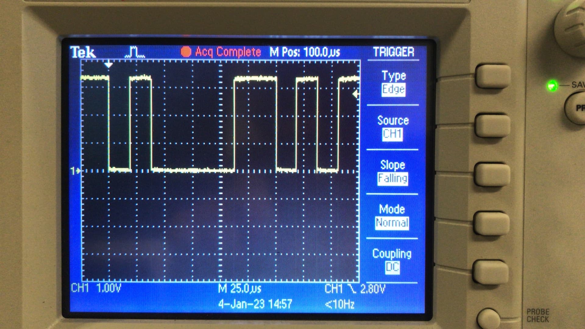
The HAL that is provided for the FE310 does not initialize the UART properly. The Documentation mentions that it is required to run the victim using a clock of 7.37MHz. However doing this the UART is not properly initialized to use a baudrate of 38400 and 2 stop bits. As can be seen in the picture below, which is a transmission of the character ‘a’ (0b1100001).
As can be seen the baudrate is higher than 38400 (<25us per character) and only one stop bit is used instead of two.
To fix the issue I have hard coded the init_uart(void) function inside of fe310_hal.c for a clock rate of 7.37MHz.
void init_uart(void)
{
    long control_base = 268513280UL; //0x10013000

    // Set UART baud rate to 38400
    // Do this by setting UART `div` register to 191
    UART_REGW(METAL_SIFIVE_UART0_DIV) = 191UL;
    UART_REGW(METAL_SIFIVE_UART0_RXCTRL) |= UART_RXEN;
    UART_REGW(METAL_SIFIVE_UART0_TXCTRL) |= UART_TXNSTOP; // Use 2 stop bits.
    UART_REGW(METAL_SIFIVE_UART0_TXCTRL) |= UART_TXEN;
}
After this change the UART works accordingly.
Hi,
Re the baud rate, we’re not typically very rigorous with this since UART is generally fine with a pretty large error on the frequency. My guess is that the desired baud rate is being fed into one of the device HAL functions, which ends up with an unfortunate round at some point.
Re the stop bits, 8n1 is correct, not 8n2, as the former is what pretty much every other CW firmware uses. Does any of our documentation suggest that there should be 8n2, just want to know so that I can fix that up.
Alex
Hi,
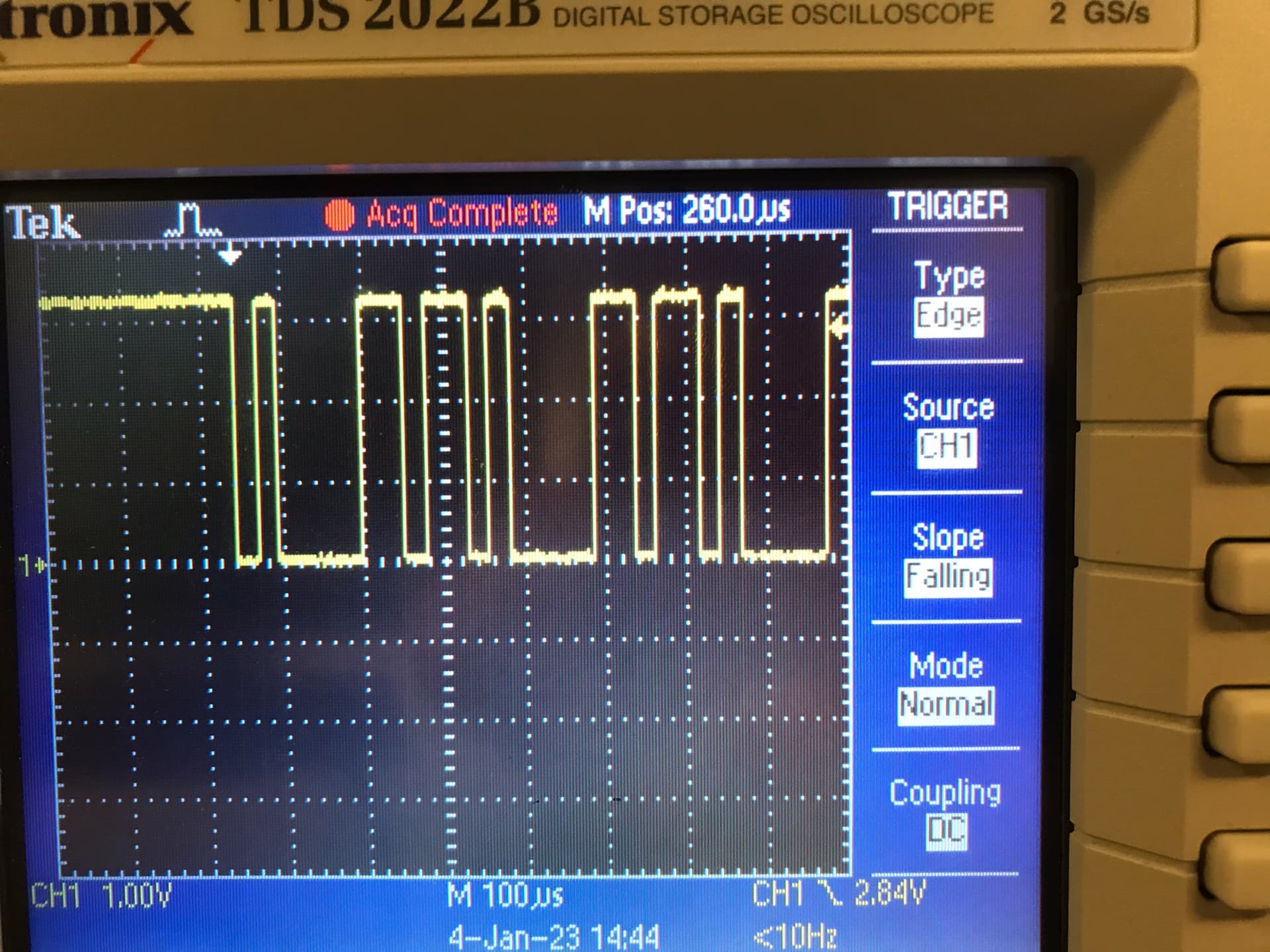
That is interesting when I compared the UART waveform with the STM32F303 it seemed like the UART was configured to be either 8N2 or 8E1. See the following image for the transmission of the character ‘a’ from the STM32F303 target:
Because of this I configured the FE310 to use 8N2, since FE310 does not have parity bit support. And with this configuration 8N2 I was able to transmit characters correctly.
The uninitialized UART’s baud rate was off by about 40%, which is significantly more than 5% (rule of thumb).
What I think is happening is that the HAL assumes the clock to be 16MHz and tries to initialize the UART accordingly. The FE310-G002 initializes the UART DIV register to use a baud rate of 115200 which is mentioned in the Manual ch18.9. For 16MHz the DIV register would be set to 139.
This is in line with my measurements and calculations. Assuming that the UART is configured for a baud rate of 115200 with a clock of 16MHz. Then for our slower clock (7.37MHz) we would see the following baud rate:
f_baud = f_in / (DIV + 1) = (7.37*10^6) / (139+1) = 52.6KHz.
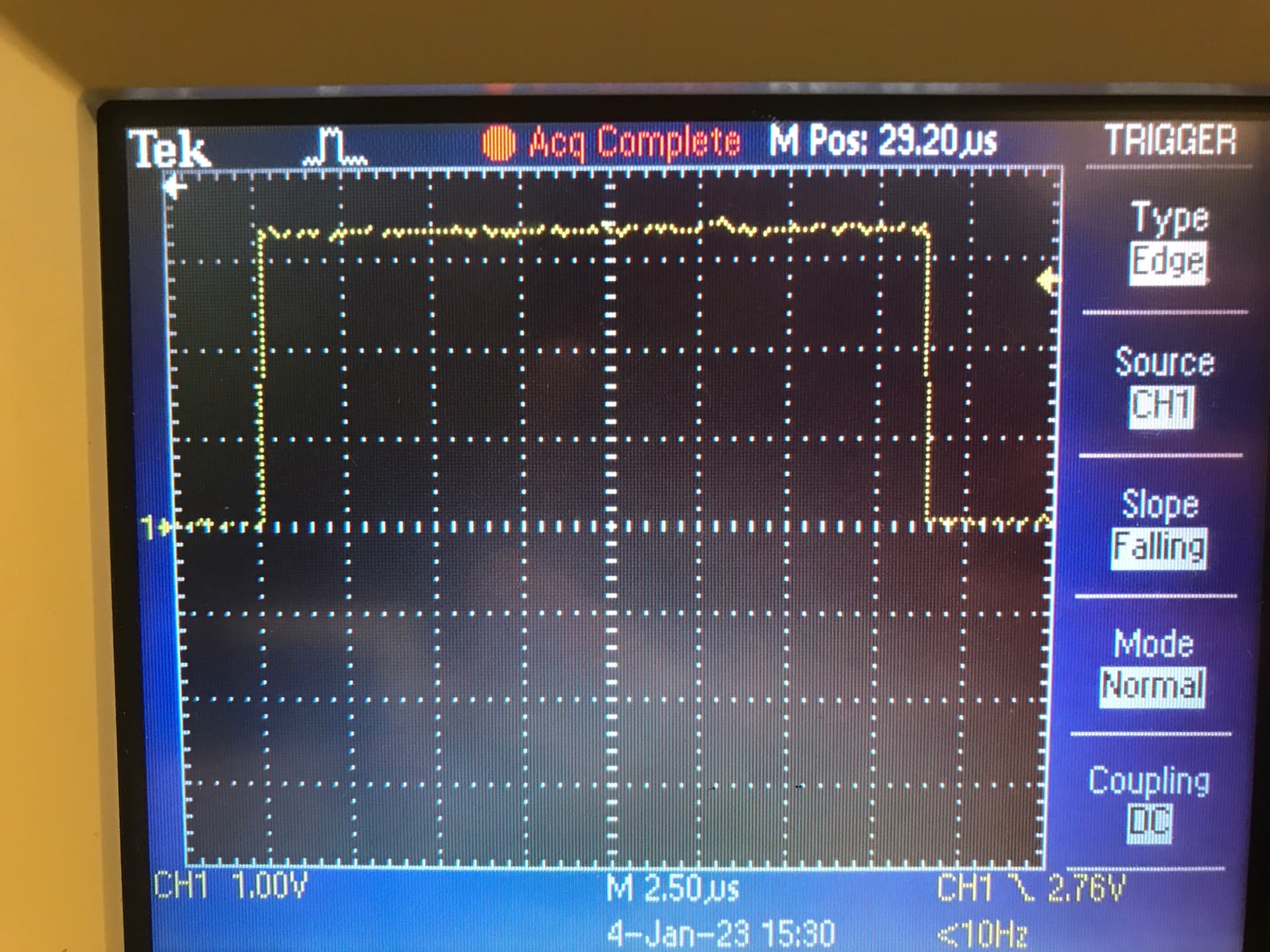
This would result in a single bit having a length of 19 microseconds, which seems to be the case in the following image, which is the transmission of a single character over UART for the FE310:
Therefore I believe that the UART is not being configured properly in the provided HAL and I think the issue is not related to an unfortunate case of rounding.
1 Like
That pause between characters is mostly from the STM32F3 HAL, not an extra stop bit. It’s only ~200 cycles to insert an extra bit, which can easily be filled up by checking flags, timeouts, doing loops, etc.
You right about the target being configured for 16MHz/115200bps. I’ll get that fixed up. Thanks for looking into that for me.
Alex
Great! thanks for the responses.