Hi,
I’m working on a research project about fault injection on the ESP32, but I’m getting some unexpected results that I’d like to discuss with you.
The board I’m using is the following: GitHub - raelize/TAoFI-Target, essentially an ESP32 with some additional conveniences. I don’t think there’s any significant difference compared to the standard CW target.
Here are the main setups I’m working with:
- In all the scenarios I’ve tested, I provide 3.3V from a stable source for all VDDs, except for the ones where I perform the glitching.
- For glitching, I use an RK6006 with different voltages (2.12V/1.8V/2.52V) depending on the tests.
- All capacitors on both VDD_CPU and VDD_RTC have been removed.
The test cases are as follows:
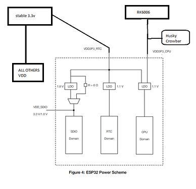
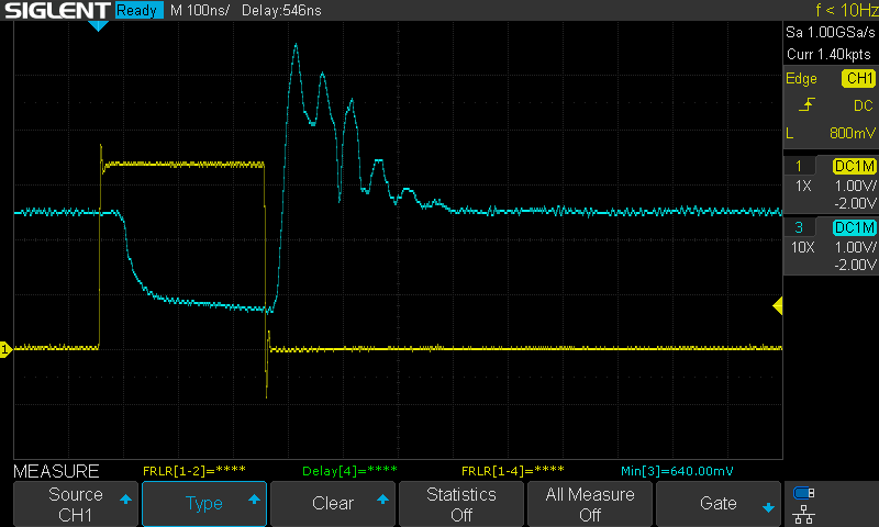
- TEST 1 - Glitching on VDD_CPU without shunt resistor
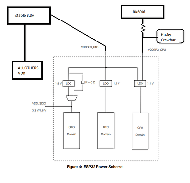
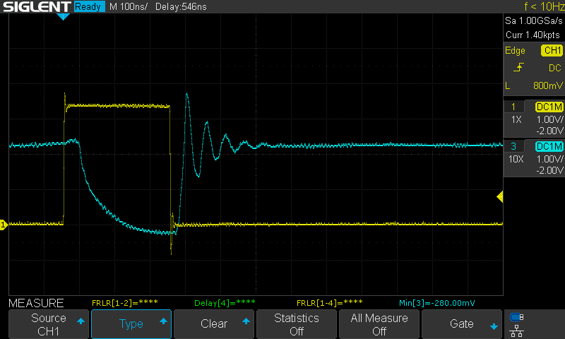
- TEST 2 - Glitching on VDD_CPU with a 10-ohm shunt resistor
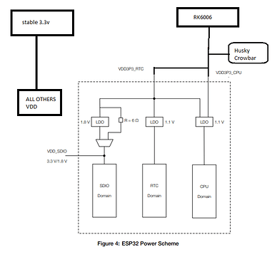
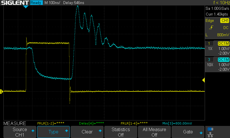
- TEST 3 - Glitching on both VDD_RTC + VDD_CPU without shunt resistor
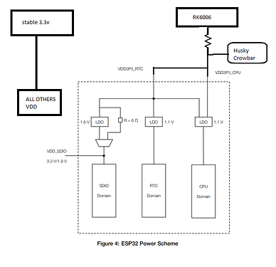
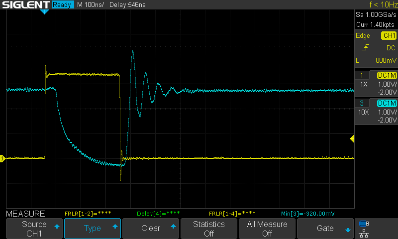
- TEST 4 - Glitching on both VDD_RTC + VDD_CPU with a 10-ohm shunt resistor
In Test 1, I barely get any faults, faults are very rare. However, in Test 2, I’m able to generate faults relatively easily.
In Test 3, I can induce faults without much trouble, and in Test 4, I’m able to glitch without issues, but with much more fine-tuned results. For example, I can flip a single bit of an instruction, something I can’t achieve in Test 3.
Can anyone explain why I’m getting such different results between the situations with or without the resistor? Is it generally better to always use a resistor in general?
What is the logic behind why it’s better to use the resistor? I was expecting better results without the resistor.
Thank you in advance
inode
