Help with UART Trigger on Husky

Hi,

As I’m having timeout problems when capturing on the SCA101-Lab2 tried to solve it by using the UART triggering feature, but there is something I don’t doing well or what I’m not understanding properly…

In the tests I made looks like ‘tio1’ triggering is not working as I would spect, while ‘tio2’ triggering give no error.

To put in situation we know in the last message received in ‘tio1’ before entering the password is "Please enter password to continue: " and next is the password sent in ‘tio2’ so following the instruccitions from ‘02 - Husky Triggers’ notebook I tried to setup uart trigger like this:
in:

scope.gain.db=21
scope.trigger.module = 'UART'
scope.UARTTrigger.enabled = True
scope.UARTTrigger.baud = 38400

#scope.gain.db = 12
scope.UARTTrigger.set_pattern_match(0, 'P@')
scope.trigger.triggers = 'tio2'
scope.UARTTrigger.trigger_source = 0
scope.UARTTrigger.rules_enabled = [0]
scope.io.glitch_trig_mcx = 'trigger'
trace_test = cap_pass_trace("P@ssW0rD\n")
scope.UARTTrigger.matched_pattern_data(as_string=True)`

Out:

'sW0rD\nP@'

Why the matched data of ‘tio2’ is reversed¿? Besides not showing timeout error when using ‘tio2’ as trigger source I am unable to see the trace of the password check seems like I am getting only random noise…

When I configure ‘tio1’ trigger I got timeout but the captured data on the trigger looks correct this time:

Resuming when I try to use ‘tio1’ as source for the UART trigger it results on timeout while capturig, but the scope.UARTTrigger.matched_pattern_data(as_string=True) command has the text as it had seen the text, but for some reason it does not trigger
With ‘tio2’ there is no problem with the triggering, but the text from scope.UARTTrigger.matched_pattern_data(as_string=True) is reversed and the plot of the captured trace is from a ‘idle’ section of the program

What I’m doing wrong? And what is more baffling for me, why ‘tio2’ matched_pattern_data is reversed compared to ‘tio1’ data?

First- if you have problems with the lab as it’s intended to be run, my strong recommendation is that those should be resolved first. If there is something wrong with your target or capture setup, trying a more complicated trigger can end up muddying the waters.

Second- UART triggering will be jittery and so not a great approach, especially for this type of attack which relies on timing differences in the power trace (the attack is definitely still doable, but without the fixed trigger it will be harder).

Third- there should be no reversal of the UART pattern match, and it certainly shouldn’t depend on whether TIO1 or TIO2 is the trigger source. Run the “UART triggering” section of the Husky Triggers demo notebook to see for yourself: chipwhisperer-jupyter/demos/husky/02 - Husky Triggers.ipynb at master · newaetech/chipwhisperer-jupyter · GitHub

Wild guess, but possibly you’ve made some changes to the capture code that result in the command being sent in reverse order to the target? That would explain why you get capture timeouts. Use a logic analyzer to see what’s actually getting sent to the target.

Hi! Thanks for your answers.

Will reply to them in order :wink:

First - I don’t want to mix issues, as the problem I’m facing capturing in this lab is happening when I don’t use SAM4S as target, I’m trying to solve that in other, but meanwhile I want to keep using and keep learning, so what I’m trying also other possible solutions, is pkausible to have such situation in real live isn’t it, having to use uart triggering I mean, so I though this would be a nice program to use the uart triggering to practice

Second - With this exercise I only want to practice the uart trigger and deep in his results, configs, etc

Third - I’ve already done that notebook, that’s why I wanted to give a try t the uart triggering with the password notebook, as it have many usart comunication, so many possible triggers :wink:
I took it as realistic scenario where I cannot have a trigger and other possible trigger were the uart thing. I followed that notebook as guide to setup the trigger on this target

Lastly, What capture code are you talking about maybe the ‘cap_pass_trace()’ function? I messed up with it to add some print(scope.gain) because some I’ve nticed about the gain.db being changed without any apparent reason after capturing, but now that lines are commented so that didn’t should interfere on this UART trigger issue, isn’t…
Whatever as said before I don’t want to mix and this gain issus is opened on another post… I’ve not modified any other capture file of function…

I will add new data to the issue: when I try to make the capture with tio1, the error lights go on and ADC errors = trigger too soon error, is shown

Attached the Logic Analyzer as you requested and looks like the trigger (I’ve conected to the Trigger/Glitch Out MCX) it is not being done when selected Tio1


But it IS when selected tio2, whay I noticed is that it only is up 100ns (maybe is a bit too low isn’t??):


There was a small bug where “trigger too soon” was reported instead of “gain too low”; apply this fix: Husky: fix scope.adc.errors reporting. · newaetech/chipwhisperer@75a8109 · GitHub

No that’s fine. The trigger output MCX carries Husky’s internal trigger signal. If there is a pulse there, it’s because Husky triggered.

Whatever code you are using to carry out the capture. Remember that I have limited visibility into your code.

I think the best way for us to help you here is for you to share a proper minimal reproducible example, as it’s defined here. Give us everything we need to reproduce the problem you’re seeing. Otherwise we can only guess and this is leading to long and confusing back-and-forths.

Wan to carify

But it IS when selected tio2, whay I noticed is that it only is up 100ns (maybe is a bit too low isn’t??):

Here I was trying to say that triggering with tio2 is working as expected, the trigger can be seen on the logic analyzer, but wanted to know if his duration (100ns) is the exected one by curiosity and also wanted to ask, why not, if we can change the trigger duration maybe make it a little bit longer like 1ms or so…

So lets start with the minimal reproducible:

I also made a video to show you what I’m doing and how I’m doing it, maybe it can also help to see wwhat is happening ;D

I’m trying to capture using UART triggering with the husky using the SAM4S as target in the notebook Lab 2_1B - Power Analysis for Password Bypass, I am able to capture using TIO2 as source trigger, but each time I try to use TIO1 as source the notebook fails with no trigger seen! Trigger forced

the Notebook is this:

SCOPETYPE="OPENADC"
PLATFORM='CW308_SAM4S'
CRYPTO_TARGET='NONE'
VERSION='HARDWARE'
%run "Lab 2_1B - Power Analysis for Password Bypass (HARDWARE).ipynb"
reset_target(scope)
scope.trigger.module = 'UART'
scope.UARTTrigger.enabled = True
scope.UARTTrigger.baud = 38400
scope.gain.db = 12
scope.UARTTrigger.set_pattern_match(0, 'P@ssW') # match 'P@ssW'... that we send
scope.UARTTrigger.set_pattern_match(1, 'ontinue:') # match 'ontinue'... that we receive
scope.trigger.triggers = 'tio2'
scope.UARTTrigger.trigger_source = 0
scope.UARTTrigger.rules_enabled = [0,1]
scope.io.glitch_trig_mcx = 'trigger'

(ChipWhisperer Scope WARNING|File TraceWhisperer.py:1367) Coudln’t achieve exact desired frequency (129981170.654297); setting to 130207492.828369 instead.

trace_test = cap_pass_trace("P@ssW0rD\n")
print(scope.UARTTrigger.matched_pattern_data(as_string=True))

WARNING:root:SAM3U Serial buffers OVERRUN - data loss has occurred.

ue:P@ssW


While running this code I have the logic analyzer connected to the MUX and to GPIO4, plus GPIO1 and GPIO2, and now it is configured to capture at any change of state at pin GPIO4

In this screenshot we can see the trigger on the MUX and also the trigger on GPIO4
few moments later so the capture with Tio2 is working propery:


After this the next cell is the capture with Tio1:

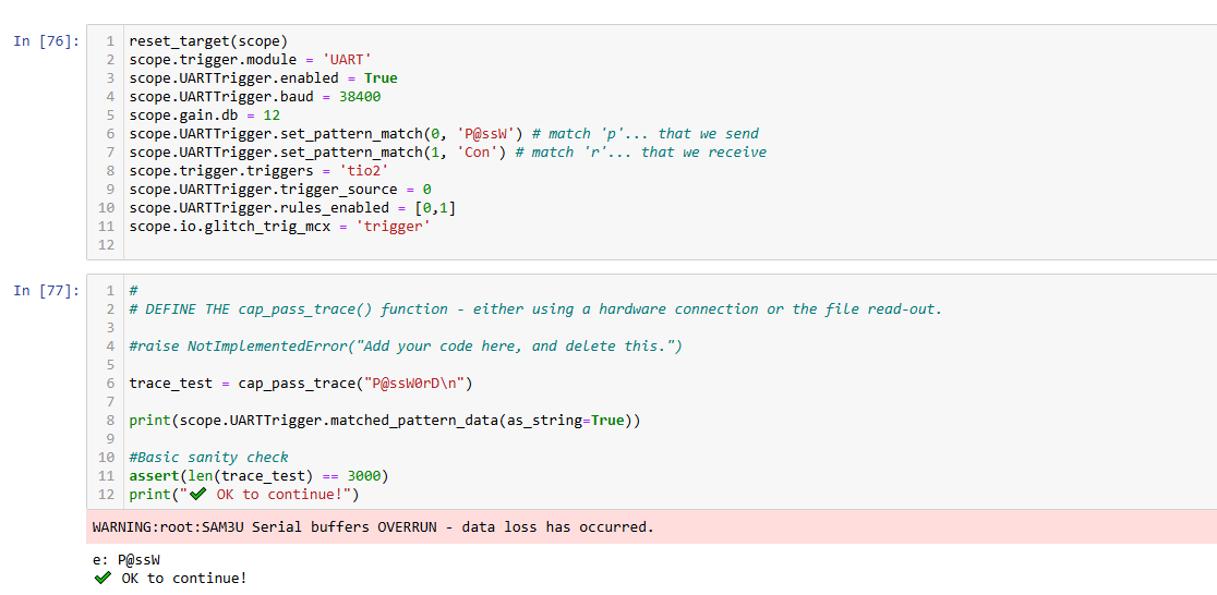
reset_target(scope)
scope.trigger.module = 'UART'
scope.UARTTrigger.enabled = True
scope.UARTTrigger.baud = 38400
scope.gain.db = 12
scope.UARTTrigger.set_pattern_match(0, 'P@ssW') # match 'P@ssW'... that we send
scope.UARTTrigger.set_pattern_match(1, 'ontinue:') # match 'ontinue:'... that we receive
scope.trigger.triggers = 'tio1'
scope.UARTTrigger.trigger_source = 1
scope.UARTTrigger.rules_enabled = [0,1]
scope.io.glitch_trig_mcx = 'trigger'

trace_test = cap_pass_trace("P@ssW0rD\n")

print(scope.UARTTrigger.matched_pattern_data(as_string=True))

WARNING:root:SAM3U Serial buffers OVERRUN - data loss has occurred.
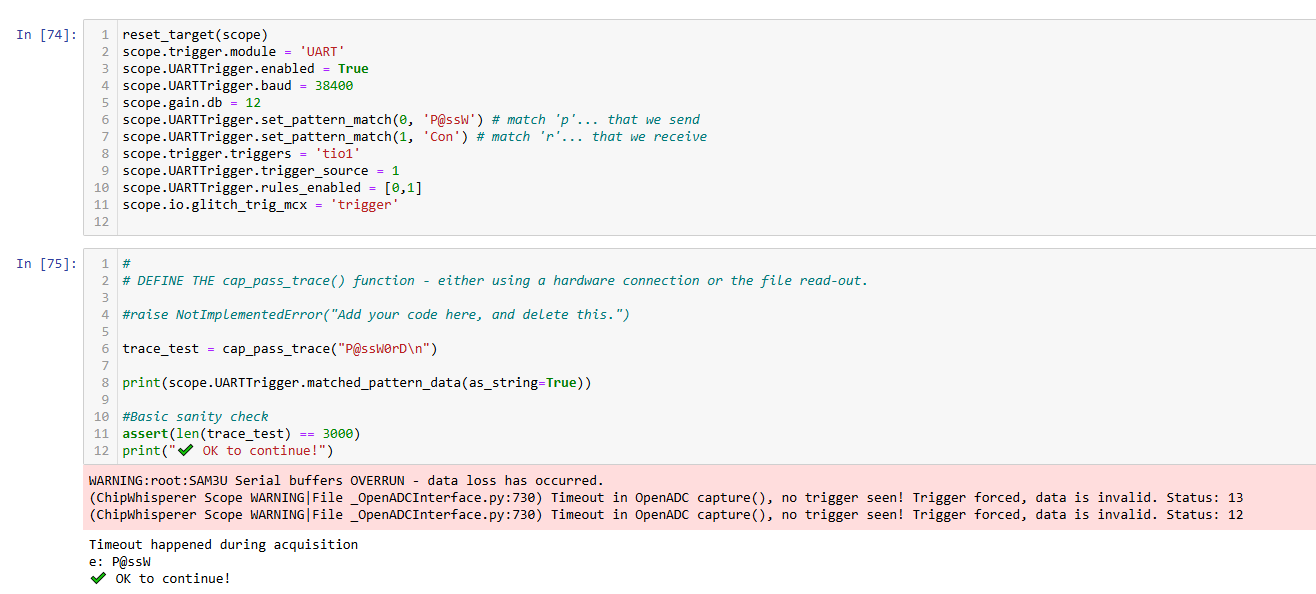
(ChipWhisperer Scope WARNING|File _OpenADCInterface.py:730) Timeout in OpenADC capture(), no trigger seen! Trigger forced, data is invalid. Status: 13
(ChipWhisperer Scope WARNING|File _OpenADCInterface.py:730) Timeout in OpenADC capture(), no trigger seen! Trigger forced, data is invalid. Status: 12


Timeout happened during acquisition
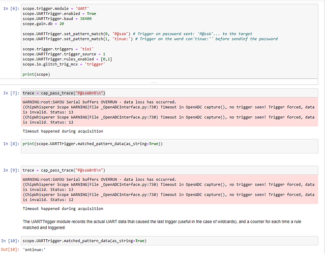
ontinue:*


Here we see that ontinue:* is printed as result of the command print(scope.UARTTrigger.matched_pattern_data(as_string=True)) which indicates configured pattern matching

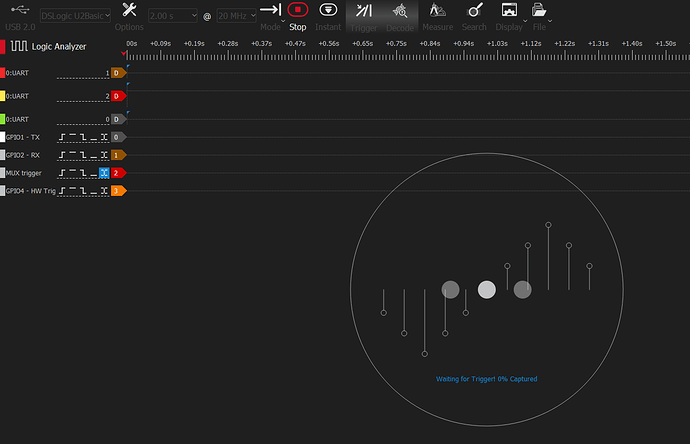
What is more extrange is that running this cell with the logic analyzer attached many times does not trigger the MUX trigger nor the GPIO4, as it were executing nothing at all…
This is the logic analyzer screen after runnin this cell and being configured to take a capture at state change of MUX pin:


The capture was not taken by the logic analyzer and the result of the notebok’s cell was:

WARNING:root:SAM3U Serial buffers OVERRUN - data loss has occurred.
(ChipWhisperer Scope WARNING|File _OpenADCInterface.py:730) Timeout in OpenADC capture(), no trigger seen! Trigger forced, data is invalid. Status: 13
(ChipWhisperer Scope WARNING|File _OpenADCInterface.py:730) Timeout in OpenADC capture(), no trigger seen! Trigger forced, data is invalid. Status: 12


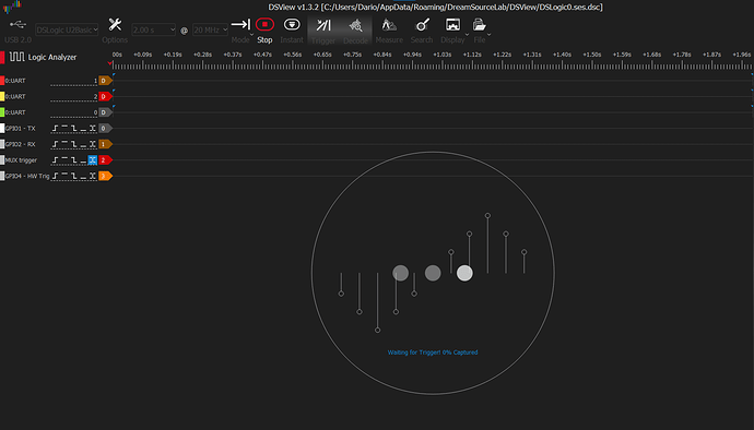
This is the screen of the logic analyzer configured to take a capture at change of state of the GPIO4 pin:


We now can see the trigger happening on MUX where it is supposed to happen which have no much sense to me as before the logic analyzer was configured to trigger on MUX and the logic analyzer got nothing, the cell result is still the same as before no trigger seen! Trigger forced

  • This is the %run “Lab 2_1B - Power Analysis for Password Bypass (HARDWARE).ipynb” code:
def cap_pass_trace(pass_guess):
    reset_target(scope)
    num_char = target.in_waiting()
    while num_char > 0:
        target.read(num_char, 10)
        time.sleep(0.01)
        num_char = target.in_waiting()

    scope.arm()
    target.write(pass_guess)
    ret = scope.capture()
    if ret:
        print('Timeout happened during acquisition')

    trace = scope.get_last_trace()
    return trace

This is the firmware flashed to the SAM4S:

int main(void)
  {
    platform_init();
    init_uart();
    trigger_setup();

    char passwd[32];
    char correct_passwd[] = "P@ssW0rD";
    //trigger_low();
    delay_2_ms();
    delay_2_ms();
    //trigger_high();
    while(1){
        
         
        my_puts("*****Safe-o-matic 3000 Booting...\n");
        //Print some fancy-sounding stuff so that attackers
        //will get scared and leave us alone
        my_puts("Aligning bits........[DONE]\n");
        delay_2_ms();
        my_puts("Checking Cesium RNG..[DONE]\n");
        delay_2_ms();
        my_puts("Masquerading flash...[DONE]\n");
        delay_2_ms();
        my_puts("Decrypting database..[DONE]\n");
        delay_2_ms();
        my_puts("\n\n");

        //Give them one last warning
        my_puts("WARNING: UNAUTHORIZED ACCESS WILL BE PUNISHED\n");
        
        trigger_low();

        //Get password
        my_puts("Please enter password to continue: ");
        my_read(passwd, 32);
        int len_pwd =sizeof(correct_passwd);
        uint8_t passbad = 0;

        trigger_high();

        for(uint8_t i = 0; i < len_pwd; i++){
            if (correct_passwd[i] != passwd[i]){
                passbad = 1;
                break;
            }
        }

        if (passbad){
            //Stop them fancy timing attacks
             int wait = 1;
            for(volatile int i = 0; i < wait; i++){
                ;
            }
            delay_2_ms();
            delay_2_ms();
            my_puts("PASSWORD FAIL\n");
            //led_error(1);
        } else {
            delay_2_ms();
            delay_2_ms();
            my_puts("Access granted, Welcome!\n");
            //led_ok(1);
        }

        //All done;
        while(1);
  }

  return 1;
  }

If you need anything else please does not hesitate on asking for it

To follow the spirit of the ‘minimal reproducible example’ I tried to run the same notebook in a brand new laptop with a fresh windows 11 install.

And I had the exact same issue when trying to get a trace using the UART module and ‘tio1’ configured as trigger, the first time fails completely but subsequent attempts also fail even though all the internal work seems to work no matter the pattern is seen and no matter mux is being triggered

Having UART trigger configured with pattern on ‘tio1’ make the capture fail, the first time you run the capture it does not detect the configured pattern, as you can see in the screenshot when printing ‘‘UARTTrigger.matched_pattern_data’’ the response is empty and the mux trigger is not seen in the logic analyzer. The second time I try to get a trace I was are able to see the pattern printed from ‘UARTTrigger.matched_pattern_data’ and also the mux trigger was fired but the capture still failed with ‘no triger seen!’ as you can see in the screenshot:

This is the captured data in the logic analyzer the first time I try to get the trace with ‘tio1’ configured (In [7] in previous screenshot), as you can see mux trigger is not fired

This is the logic analyzer captured data during the second trace being captured (In[9] in previous screenshot) here we can see the mux being triggered. But the trace still failing with ‘no trigger seen!

This is the notebook, the hex, bin and the bassic_passwordcheck.c files:
BasicPwd-UART_tio1.zip (2.3 MB)

P.D. Also no matter what value do you put in ‘gain.db’ that always after failing to get a trace with ‘tio1’ the error light starts flashing and ‘ADC errors’ equals to 'gain too low error ’

Triggering on tio1 fails because the target is putting out the “continue:” message on power-up, prior to reading the password. Husky doesn’t trigger because it’s not armed when “continue” is seen. A scope needs to be armed before it can trigger.

If you want to match on TIO1, use something from the password response string instead, like “FAIL” or “Welcome”. That works as expected for me.

If I set scope.gain.db to 25, I don’t get gain errors. Make sure you’re not inadvertently resetting it to 12 elsewhere in your code.

Thank’s didn’t know that detail :wink:

So no matter if the pattern is recognized or if the mux is triggered, because if this happens before running scope.arm() then the trigger will be ignored.

Using ‘tio1’ pattern with “acces granted” or “access denied” messages would be useless for this exercise, because all the password checks we are trying to evade are already finished when that messages are sent through uart, so I tried to move the scope.arm() call in the function to have it active when the ‘continue:’ message is printed:

def cap_pass_trace(pass_guess):
    reset_target(scope)
    scope.arm()
    num_char = target.in_waiting()
    while num_char > 0:
        target.read(num_char, 10)
        time.sleep(0.01)
        num_char = target.in_waiting()

    
    target.write(pass_guess)
    ret = scope.capture()
    if ret:
        print('Timeout happened during acquisition')

    trace = scope.get_last_trace()
    return trace

This half-worked, I say half-worked because with target SAM4S the error trying to capture ‘tinue:’ with ‘tio1’ is still there, but running the same notebook with STM32L5 (the other target I have that can be directly programmed with the husky) the error dissapear.

One thing I noticed with both targets is that the first time you run the capture it is unable to recognize the pattern, I need to run it twice for the pattern to be matched and trigger the mux?

In the ‘02 - Husky triggers’ says that ‘The trigger fires after the last pattern byte is received’ and also there is a few cycles of delay after the last byte of the pattern and the trigger, so there won’t be much difference between

As we see the pattern of ‘tio2’ is working as expected and with ‘P@ssW’ configured as pattern I can see the MUX trigger being fired between the ‘W’ and the ‘0’ a few miliseconds before the actual GPIO4 trigger: (1.054647ms when using SAM4S and 1.0912ms with STM32L5)

So af far as I was understandig was expecting to have a capture with more ‘data’ before start idling than the capture got when using the basic trigger.
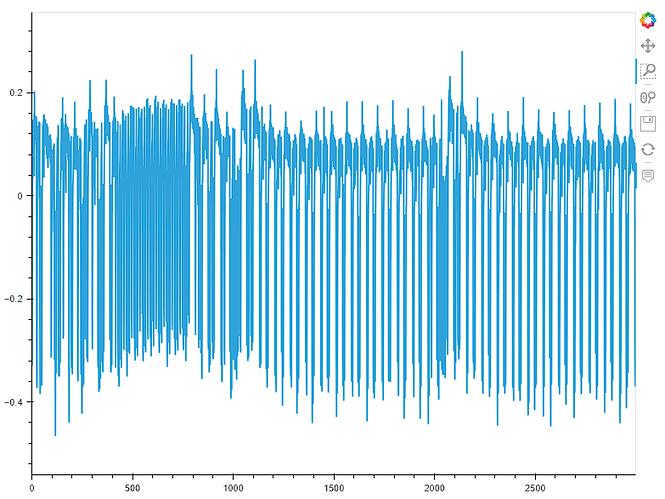
This is the plot of the capture when sending the correct password to the SAM4S and we can see that it starts idling at aprox 2100 samples:

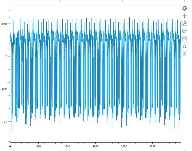
But when I plot the captured trace done with ‘tio2’ what I see is a ‘little action’ just a few cycles before start idling:

What is the question? If it’s “how to make the password attack to work”, then triggering on the target’s boot-up message is really not the best approach, because this will have all the layers of delay and jitter - from the target’s firmware all the way up to the Python interpreter!

A better approach would be to trigger on the candidate password that you are sending, since this at least removes all the delay and jitter that your host PC is otherwise adding.

My first reply bears repeating:
“UART triggering will be jittery and so not a great approach, especially for this type of attack which relies on timing differences in the power trace (the attack is definitely still doable, but without the fixed trigger it will be harder).”