Hi there, I got the ChipWhisperer Lite and want to connect the I/O pins to a target that runs on 1.6V. So I built a voltage divider using 200k ohm resistors and drove it with pins 18 (+3.3V) and pin 17 (GND). Then I connected pin 8 (VREF) to the middle of the divider (1.6V), but the I/O pins still delivered 3.3V. After studying the schematics, I desoldered SJ6, soldered three pins to JP5 and connected TVREF with the pin in the middle.
However, as soon as I connect pin 8 (VREF) to the voltage divider, the power of pin 18 dropps to something around 0.2 V.
Yes but we don’t recommend or support this. You would also need to regenerate the FPGA bitfile to modify its I/O pad settings. This is where the “easy to damage the FPGA” part comes in:
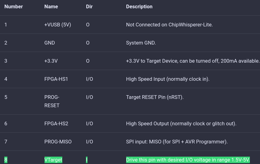
JP5 selects the IO voltage for the FPGA bank which connects to the 20-pin target. By default SJ6 selects this to be 3.3V. It is not recommended to change this, as it is easy to damage the FPGA by feeding an out-of-range voltage in.
So again we recommend our CW506 breakout board, which can be configured to set its voltage translators to the voltage provided on that VREF pin.