We are trying to generate glitch to see if target board’s glitch detector activates, but not sure if Husky outputs the glitch. Thought it would be simple setting up glitch to external trigger on GPIO4, but we are perplexed on not seeing the voltage fall down.
Glitch generation is enabled on HP GLITCH
I can see that via Trigger MCX shows that glitch is enabled at times, but we can’t see on 100 MHz 1GSa/s oscilloscope the actual short from the glitch port. The voltage just “waves sligthly at end”.
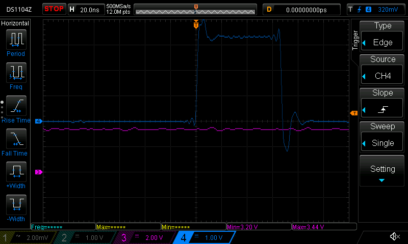
Glitch enable times are around 35-70 ns as shown below. HP GLITCH is used. Blue color is the glitch enable, magenta is trigger.
The HP GLITCH MOSFET is IRF7807TRPBF (Access to this page has been denied.) and has rise+fall time 17+6 ns, which is about 43.5 MHz, so can’t open fully faster than that, thus we should be able to see something on 100 MHz scope. That is not counting in also turn-on+turn+off time, which is 12+25 ns. So 60 ns should open fully the MOSFET.
One 35 ns glitch from a repeat:
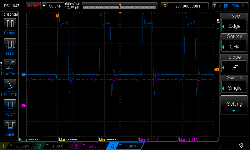
Repeated 35 ns glitches (zoomed out the previous image)
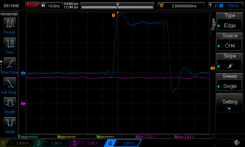
Doubled the width, now about 70 ns width - this should make the MOSFET open fully, see
Code to accompany so you can see settings
Now I am using it with CW313 and SAM4S from Husky package to try determining what I’m doing wrong.
Setup is the generic script.
import chipwhisperer as cw
%run "../../Setup_Scripts/Setup_Generic.ipynb"
scope.io.glitch_trig_mcx = "glitch"
scope.glitch.enabled = True
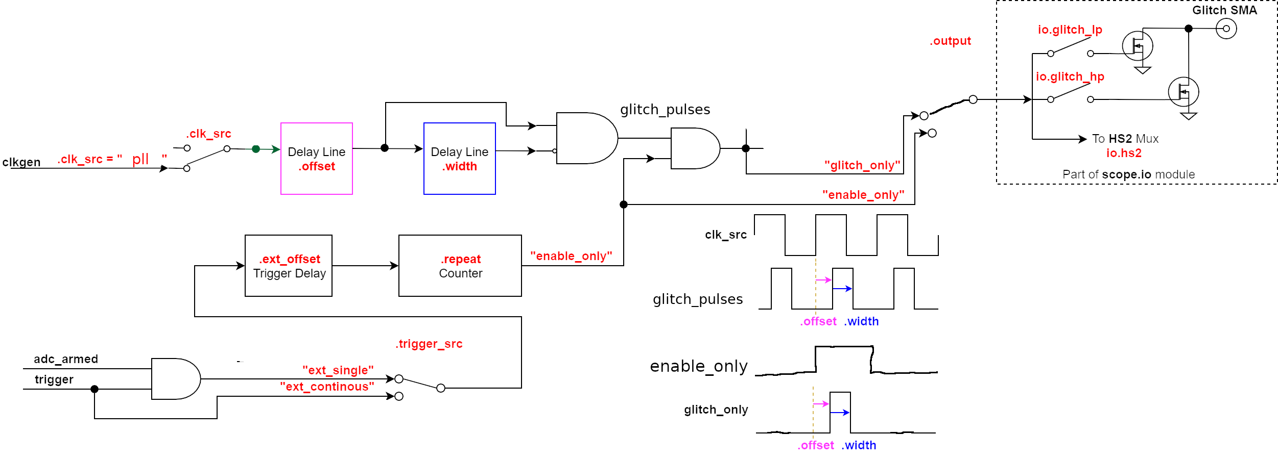
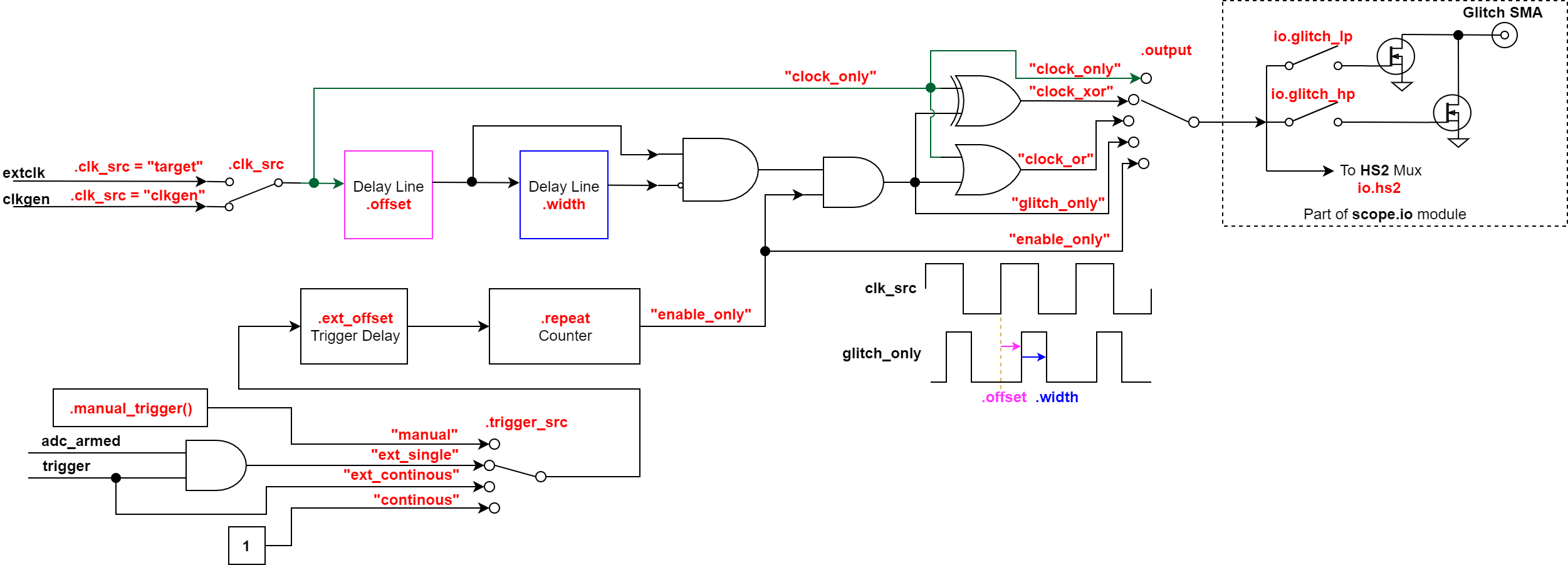
scope.glitch.clk_src = 'pll'
scope.clock.pll.update_fpga_vco(600e6)
scope.glitch.output = 'glitch_only'
#scope.glitch.output = 'enable_only'
scope.glitch.trigger_src = 'ext_single'
scope.glitch.repeat = 20
#scope.glitch.arm_timing = "before_scope"
assert scope.glitch.mmcm_locked
print(scope.glitch.phase_shift_steps)
4592
Width and offset setting:
scope.glitch.offset = 0 - 0*scope.glitch.phase_shift_steps
scope.glitch.width = 200000 # - 400000 causes ADC clipped #100
print(f"offset {scope.glitch.offset}, width {scope.glitch.width}")
offset 0, width 200000
200k equals those about 35 ns glitch enable, 400k about 70 ns. The 400k width causes ADC clipping (maybe this is a note to see that it really output the glitches?) 800k for some weird reason clips back to width of maybe 10 ns enable (???)
Using SCOPE_GAIN 18 here, use GPIO4 as trigger
print("Using scope gain", SCOPE_GAIN)
scope.gain.db = SCOPE_GAIN #12
scope.adc.samples = 120000 #50000 #120000
scope.adc.presamples = 10000
scope.trigger.module = 'basic'
scope.trigger.triggers = 'tio4'
scope.arm()
Run the capture which raises the GPIO4, trigger causes glitch enable signals to show:
trace = cw.capture_trace(scope, target, bytearray(16), bytearray(16))
print(scope.errors)
With width at 200k, it goes through without any error, using width 400k causes ADC clipping and the clipped signal when graphed with bokeh looks like:
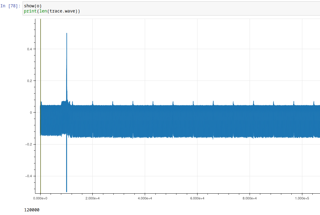
Is the tall vertical line the glitch we were not able to see on the scope? Since the Y axis is without units and centered, not sure I am looking at voltage fall/short. But since it’s measured over shunt, then it would make sense that it’s short which puts high peak of current for some time.
Glitch width vs repeat on Husky
Repeat and width on Husky is something that I can’t wrap my head right even after multiple reads of the settings documentation. You can have one wide glitch or repeat with some limitation? I’d probably rather want single wider glitch, I can’t quite see how repeat constrains width.