I noticed that there is inconsistency between the ‘trig_count’ value and the trace plot for the iCE40 FPGA target board. The CW Husky is used to capture the traces for the official demo located at ‘demos/PA_HW_CW305_1-Attacking_AES_on_an_FPGA.ipynb’
‘scope.adc.trig_count’ returns the integer ‘44’
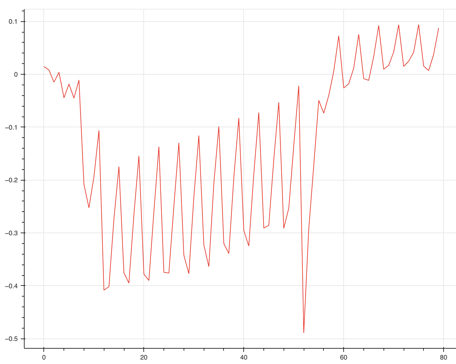
But the captured trace reveals that the AES operation is up to 55 samples.
Actual leakage happens in the range 50 - 55 samples. So, inconsistency is Husky returns an active period equal to [0 … 44] but AES leakage is beyond this range ([50 … 55]).
If you looked at the target source, you’d see that the target raises the trigger line when it begins encrypting, and lowers it when it’s done. scope.adc.trig_count returns the number of ADC clock cycles that the trigger line was seen high for, and it does so accurately.
Yes, this part is clear. The AES itself is surrounded by kind of trigger_high and trigger_low.
This part is also clear.
Unclear part is “if ADC counts its ticks and each tick actually causes sampling, how the tick numbers (when AES key is leaked) go beyond of trigger_low”?
In other words, trigger_low means “AES was already finished”. Trigger_low happens when ADC counts 44 ticks but the AES key is leaked at 50-55 samples (at the moment when trigger_low happened many ticks ago).
Your question isn’t totally clear, but if you’re asking why samples are collected after the trigger is low: the answer is that CW doesn’t necessarily capture samples when the trigger line is high (although it can be configured to do so).
In most of our examples (including the FPGA AES one here), the capture begins when the trigger line goes high and finishes after scope.adc.samples samples have been collected, regardless of whether the trigger line is still high or not. If you want, you can run a single capture to see how long trigger is high for, then set scope.adc.samples = scope.adc.trig_count. You can also have the capture start before or after the trigger with scope.adc.presamples / scope.adc.offset.
There is also some latency between when the trigger line goes high and when the first sample is collected. First, the ADC itself has a 10-cycle latency (see the TI ADS4128 datasheet). Then, there is an additional 4-cycle latency from when the Husky FPGA sees the trigger line high to when it starts storing incoming ADC samples.
Yes, the trigger_low is just a hint for us to understand that AES has been finished.
I did it. The result is the round key cannot be guessed as sampling is stopped too early (because scope.adc.trig_count is 44 but as I said the state being leaked must be fit to 50 - 55 samples.)
Is this 4-cycle latency a part of Husky’s FPGA code to guarantee filling of ADC’s pipeline?
That’s just how it works. There’s a lot going on in the logic surrounding this (multiple triggers, configurable offset for starting the capture before or after the trigger, and all the other capture options that you see in scope.adc). Given that the external ADC chip itself has a 10-cycle latency, it wasn’t a design goal to make the FPGA’s capture latency lower.
@jpthibault Is my understanding correct that the main delay is due to ADC latency?
The trigger_low can tell us the scope.adc.trig_count value but this trig_count ignores ADC’s delay when we use it as scope.adc.samples. Ultimately, all data in the ADC’s pipeline is ignored and we miss last 2 rounds.
The capture latency is 14 samples; set your capture parameters correctly and no data will be lost
(or just keep to the defaults used in our AES FPGA notebook).
I want to make sure I understand this latency correctly. Are you saying that once the tio_trigger goes high, the following 3.5 clock cycles (14 samples, clocking at x4) are missed by the ADC?
Adding a bit more to this because it’s not necessarily intuitive (even I get tripped up by this sometimes), and 14 isn’t correct.
There are two components to the latency: the ADC chip’s latency (10 cycles), and the FPGA’s storage latency (4 cycles).
The ADC chip’s latency is actually a negative latency for our purposes. Its 10-cycle latency means that when the trigger line goes high, the sample coming out of the ADC is what was sampled 10 cycles in the past. So, the latency is not 10 + 4; it’s -10 + 4 = -6 cycles.
I should do a proper illustration of this, but hopefully this helps visualize it. Here when the trigger happens on sample #10, the first sample that is stored is sample #4:
Thanks a lot, that diagram is really helpful. If I understand correctly then, when using the Husky you should actually set scope.adc.offset = 6 to align the trace with the waveform (in the sense that the first sample of the trace corresponds to the rising edge the tio_trigger).
However, I notice in the CW305_AES_pipelined.ipynb file, the scope.adc.offset is changed depending on the particular target board as opposed to the capturing device (it is set to 0 for the CW305 and set to 6 for the CW312). But based on this conversation, it seems like the latency is a product of the ADC, and therefore of the capturing device rather than the target board.
I can’t recall why scope.adc.offset would be set differently in the pipelined notebook; that’s possibly a typo.
That would not be my recommendation. The only (other) notebooks that use scope.adc.offset to account for latency differences are the sca204 series, which look at leakage on very specific samples.
When having to look at power on very specific cycles and switching between Husky/Lite/Pro capture equipment, yes you’ll have to adjust scope.adc.offset. But typically, when the trigger goes high is not exactly where you are looking to exploit leakage.
That is exactly what I’m doing! I understand that this is not the primary use case, but it is beneficial for me to align my traces with the waveforms as closely as possible.
If I might trouble you for one more thing in this thread, would you mind supplying the latency for the the CW Lite and Pro? I imagine both their ADCs as well as their FPGA latency are different from the Husky.
No. As illustrated above, if we label the ADC sample that is taken when the trigger goes high as “sample 10”, the first stored sample will be sample 4. In other words, it’s 6 samples back in time.