Lots of background noise on the CW305

Hi,

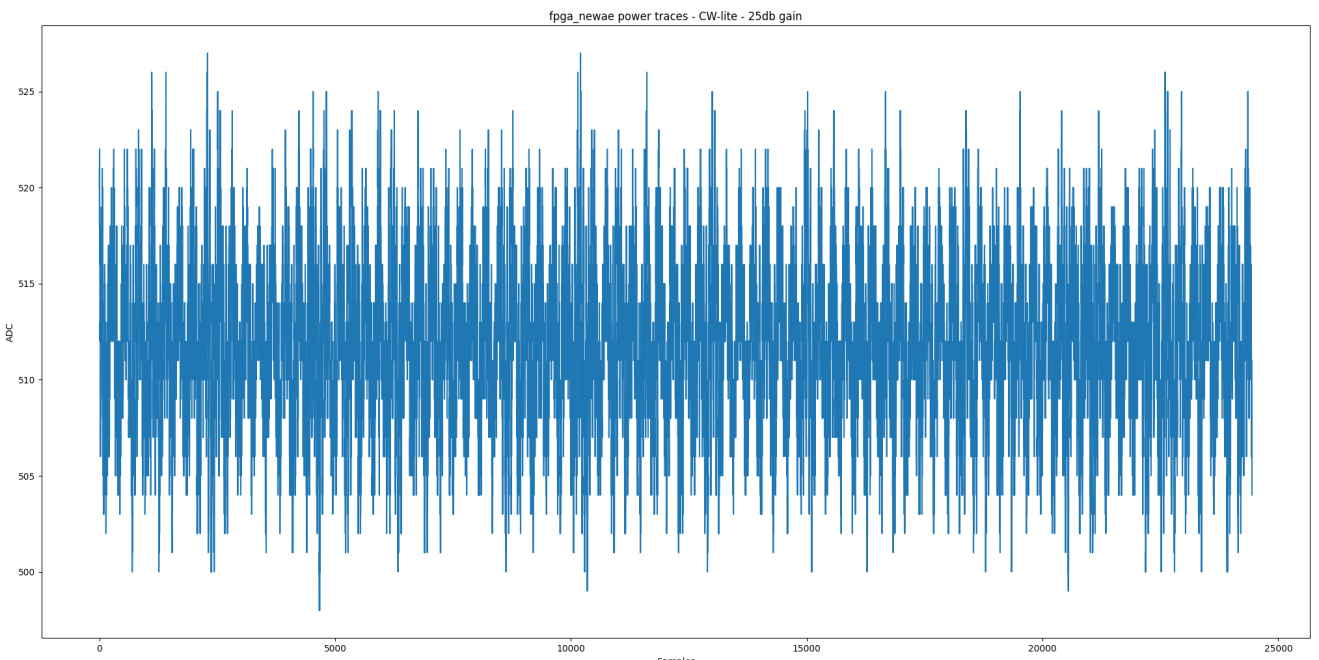
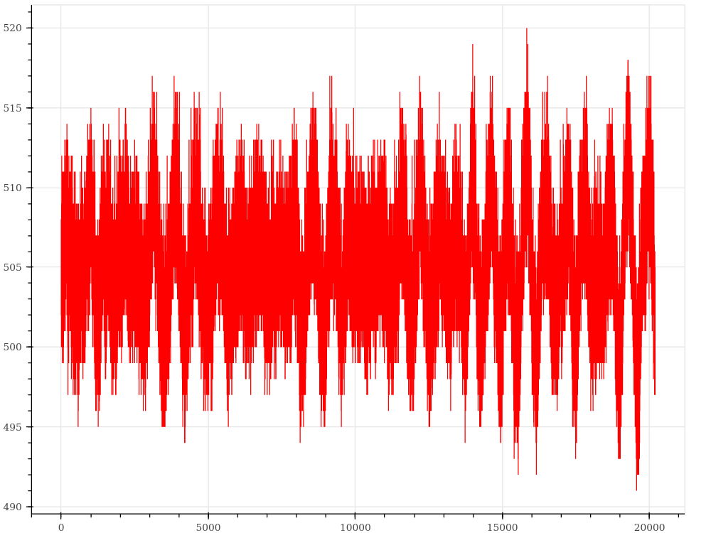
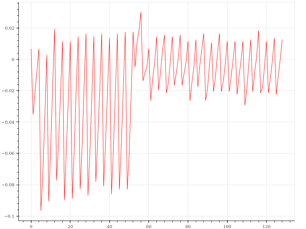
We recently noticed that we were getting fairly low SNR for CW305 measurements. As an experiment, we programmed the FPGA on the CW305 with only a counter instantiated to measure the background noise. We are surprised with the result:

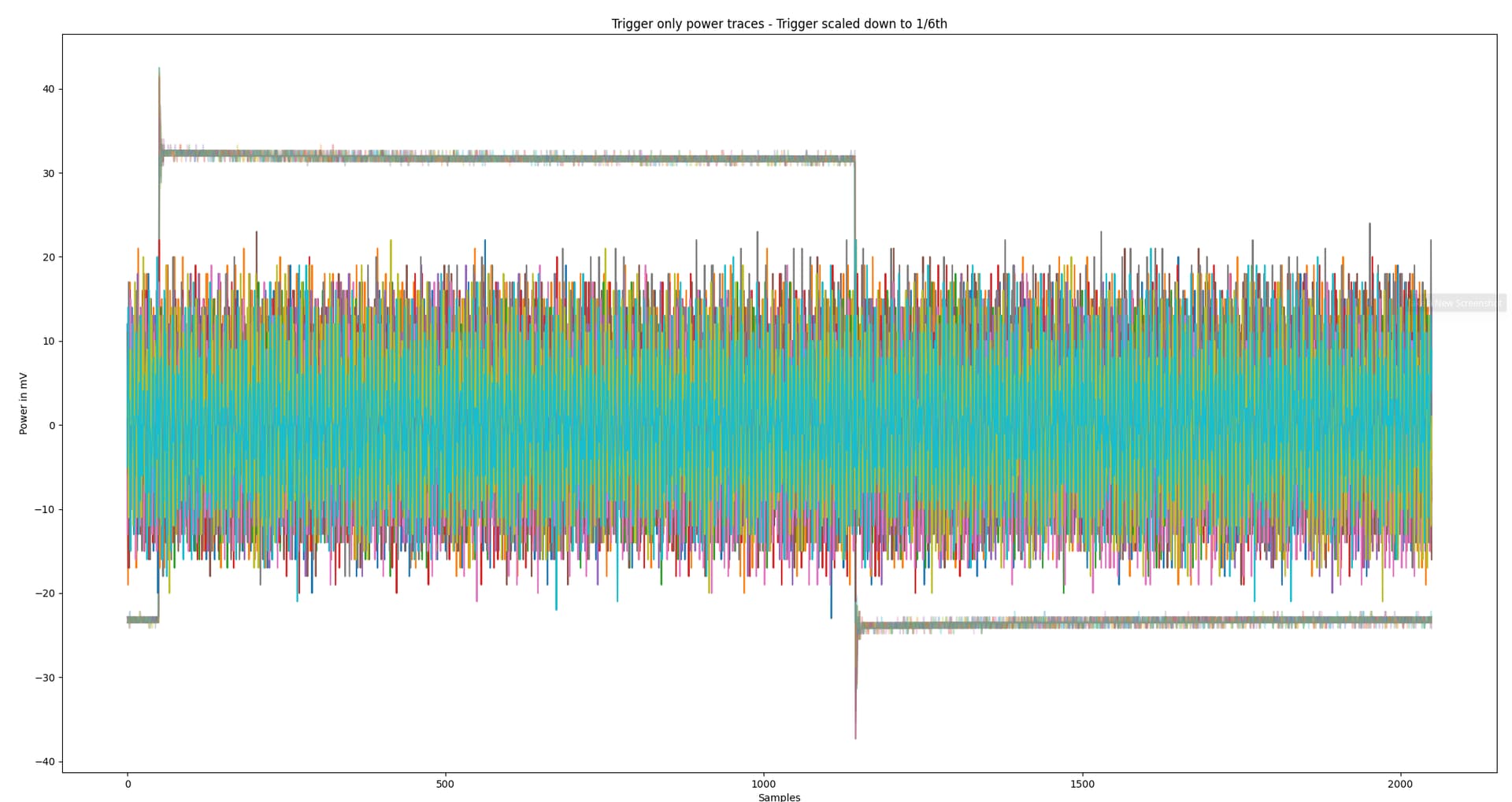
Here we measured 10 power measurements of a counter on the FPGA with a 6000 series PicoScope. The background square signal is the trigger. The power probe is a 10X probe measuring with 100mV/div and AC coupling.

The background noise seems really high (+/- 20mV). We are unsure what could be causing this and if anyone else can replicate it, or if this is expected. Please let me know if you need any additional info/experiments to help debug this!

Here is our verilog HDL for reference:

module cw305_top #(

        parameter DELAY = 1000
    )(
        // USB Interface
        input wire                          usb_clk,        // Clock
        inout wire [7:0]                    usb_data,       // Data for write/read

        
        input wire [pADDR_WIDTH-1:0]        usb_addr,       // Address
        input wire                          usb_rdn,        // !RD, low when addr valid for read
        input wire                          usb_wrn,        // !WR, low when data+addr valid for write
        input wire                          usb_cen,        // !CE, active low chip enable
        input wire                          usb_trigger,    // High when trigger requested

        // Buttons/LEDs on Board
        input wire                          j16_sel,        // DIP switch J16
        input wire                          k16_sel,        // DIP switch K16
        input wire                          k15_sel,        // DIP switch K15
        input wire                          l14_sel,        // DIP Switch L14
        input wire                          pushbutton,     // Pushbutton SW4, connected to R1, used here as reset
        output wire                         led1,           // red LED
        output wire                         led2,           // green LED
        output wire                         led3,           // blue LED

        // PLL
        input wire                          pll_clk1,       //PLL Clock Channel #1
        //input wire                        pll_clk2,       //PLL Clock Channel #2 (unused in this example)

        // 20-Pin Connector Stuff
        output wire                         tio_trigger,
        output wire                         tio_clkout,
        input  wire                         tio_clkin
    );

    wire resetn = pushbutton;
    wire reset = !resetn;

    reg[32-1:0] delay_counter;
    reg trigger_status;

    always @(posedge pll_clk1) begin
        if (reset) begin
            delay_counter <= 0;
            trigger_status <= 1;
        end else begin    
            if (delay_counter > DELAY) begin
                delay_counter <= 0;
                trigger_status <= !trigger_status;
            end else begin
                delay_counter <= delay_counter +1;
            end
        end
    end
        
    assign tio_trigger = trigger_status;

endmodule

Do you have a ChipWhisperer? It would be useful if you could measure these power traces with a ChipWhisperer, and share the bitfile with us so we can do the same on our side, to diagnose whether there is a problem with your CW305 board.

Jean-Pierre

@jpthibault We took this measurement of the same circuit with the CW-Lite. Not sure if the y-axis scale can be converted to mV.

No, the measurements are not calibrated. If you could zip up your bitfile, notebook, and traces, I can compare to what I get on my known-good CW305 board.

You could also check whether our CW305 AES demo attack works as expected: chipwhisperer-jupyter/PA_HW_CW305_1-Attacking_AES_on_an_FPGA.ipynb at master · newaetech/chipwhisperer-jupyter · GitHub

Thanks for the quick reply. Attached is the bitfile, traces and the python code.

Thanks,
project.zip (168.2 KB)

I had to make a correction to your script because CW-lite can’t lock onto a 1 MHz clock (check scope.clock.adc_locked, or the red LED on your CW-lite). So with the clock at 10 MHz I obtain something similar to you:

TBH I’m not sure what you would expect to see here. There is going to be “noise” from the clock toggling every cycle, and there is going to be some amount of noise from the rest of the system.

Does our HW AES attack notebook (linked above) succeed for you? Here’s what one of those traces look like: