Hello, I have been exploring the CW-Lite and have started looking into analyzing/attacking a third-party board, containing a Silicon Labs EFR32FG23 chip. I was hoping to get some clarification to the nature of the shunt resistor; when it should be used and the placement of it. Both when using the CW-Lite and when using an oscilloscope.
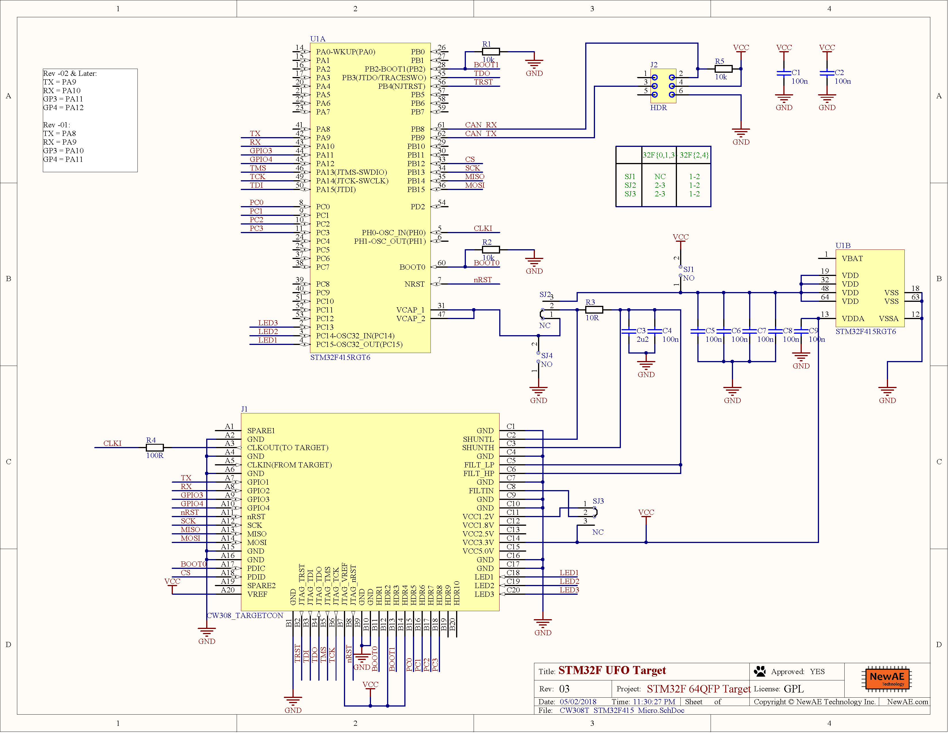
First, I have been looking into some schematics, supplied by NewAE, for target boards for the CW308 board(to clarify, I’m not using these target boards or the CW308):
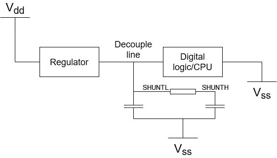
Both on the nRF52840 board(target schematic) and the EFR32MG21 board(target schematic), a shunt resistor has been placed on the decoupling lines. My first assumption, and from what I’ve read online, is that these decoupling lines often are connected to rails that power CPU and digital logic, and that we use these lines as a place for measurement since we are interested in the power consumption of the digital logic/CPU. Is this correct? By using that assumption I drew a schematic of the nRF target board, seen below. How does this work? Now the shunt is in parallel with the digital logic, and I assume we want to be in series with it? Probably it is just my electronics knowledge that is a bit rusty.
Secondly, on a blog named LimitedResults, the writer attacked the same mentioned nRF board and a different EFM32 board. I was only allowed to add two links in my post, so sorry for not linking to his blog posts:
On both of these attacks, he connected his oscilloscope directly to the decouple lines, without inserting any shunt resistors, and seemingly getting pretty decent power traces. This goes against what I’ve read about in the forums posts here and “The HW Hacking Handbook”, seemingly that you need/should insert a shunt resistor. So my question here is, is the nature of the shunt resistor only to improve the traces? Would you have any idea why the shunt was not necessary in the LimitedResults attack? LimitedResults mentions that he uses an amplifier to improve his traces(I guess this is comparable to the Gain the CW-Lite have?).
Also, LimitedResults only uses his traces to know where he should glitch, not to do any DPA or CPA attacks which is what I’m interested in exploring.
Thanks!