Hi,
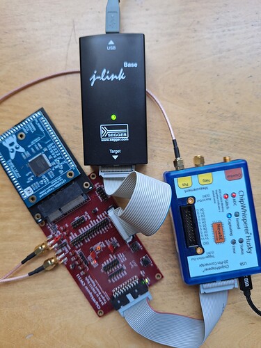
I am using the Husky and the LPC55S69 target with a CW313 adapter.
I have not been able to program firmware on the target.
I found a link here that mentions an external programmer is needed. I tried the OpenOCD patch link there and rebuilt the openocd binary. Bit it fails with the following message.
Error: unable to select a session transport. Can’t continue.
Could you please tell me what is required, in hardware and software, to program the target?
Thanks for your help
What JTAG/SWD debugger are you using? We’ve confirmed that this target works with Segger J-Link debuggers, so if you want to be sure, you can get one of those.
I have got the Segger J-Link. I connected it to the 20-pin JTAG/SWD connector on the CW313, ran JLinkExe and got the following output. From the 0V for VTref, it seems that the connection is not right.
Sorry, I am not familiar with this.
SEGGER J-Link Commander V8.60 (Compiled Aug 13 2025 12:13:07)
DLL version V8.60, compiled Aug 13 2025 12:12:03
Connecting to J-Link via USB…O.K.
Firmware: J-Link V13 compiled Jul 21 2025 13:16:03
Hardware version: V13.00
J-Link uptime (since boot): 0d 00h 11m 28s
S/N: 53001634
License(s): GDB
USB speed mode: High speed (480 MBit/s)
VTref=0.000V
Type “connect” to establish a target connection, ‘?’ for help
J-Link>
VREF should be directly connected to VCC. Is the 3.3V light on the CW308 illuminated and do you have the 20-pin connector the right way around?
Alex
I am using a CW308 to CW312 adapter. The following is how I connect them together, which appears to be the only way. Thanks.
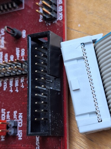
I believe your 20-pin debug connector is backwards. Pin 1 is on the outer edge of the CW313.
Because of the tab on the cable’s end, there seems to be only one way to insert it.
Sorry, nevermind, was difficult to tell from your original picture. Pin 1 on the bottom right should be VREF, can you check that with a multimeter and verify that it’s 3.3V? If not, you may need to connect VREF to J-VREF on the large 30-pin header.
No voltage on Pin 1. But J-VREF on the 30-pin header has not voltage either.
It might be that VREF and J-VREF aren’t connected on the CW308-CW312 board. Can you connect them manually on the 30-pin connector?
VREF on the 30-pin header has no voltage either.
On the Target Board, there is a line “Enable 1.2V and 3.3V Regulators”".
Does it mean anything?
I’m quite confused. Looking at the schematics of the adapter and the LPC board, there should definitely be 3.3V on both VREF and J-VREF. Can you check the solder connection between the LPC target board and the CW308/CW312 adapter? Additionally, can you check continuity between the pin labelled VCC on the far side of the LPC board (by SWCLK) and J-VREF on the CW312?
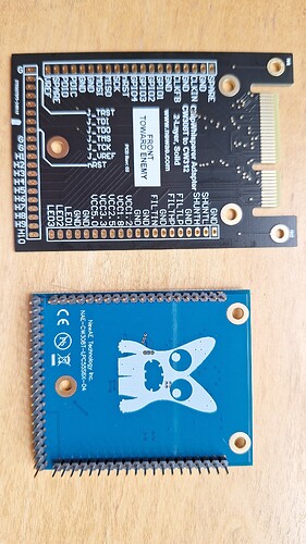
It turns out that the LPC board cannot be inserted all the way into the CW308/CW312 adapter.
If it is inserted half way, then there is 3.3V on JTref.
However, I tried connecting to the target, it is still giving errors.
$ JLinkExe
SEGGER J-Link Commander V8.60 (Compiled Aug 13 2025 12:13:07)
DLL version V8.60, compiled Aug 13 2025 12:12:03
Connecting to J-Link via USB…O.K.
Firmware: J-Link V13 compiled Jul 21 2025 13:16:03
Hardware version: V13.00
J-Link uptime (since boot): 0d 00h 07m 56s
S/N: 53001634
License(s): GDB
USB speed mode: High speed (480 MBit/s)
VTref=3.346V
Type “connect” to establish a target connection, ‘?’ for help
J-Link>connect
Please specify device / core. : LPC55S69_M33_0
Type ‘?’ for selection dialog
Device>
Please specify target interface:
J) JTAG (Default)
S) SWD
T) cJTAG
TIF>J
Device position in JTAG chain (IRPre,DRPre) : -1,-1 => Auto-detect
JTAGConf>
Specify target interface speed [kHz]. : 4000 kHz
Speed>
Device “LPC55S69_M33_0” selected.
Connecting to target via JTAG
ConfigTargetSettings() start
Disabling flash programming optimizations: Compare, SkipBlankDataOnProg
ConfigTargetSettings() end - Took 24us
InitTarget() start
ERROR: Wrong DM-AP IDCODE detected: 0x00000000
InitTarget() end - Took 858us
Connect failed. Resetting via Reset pin and trying again.
ConfigTargetSettings() start
Disabling flash programming optimizations: Compare, SkipBlankDataOnProg
ConfigTargetSettings() end - Took 39us
InitTarget() start
ERROR: Wrong DM-AP IDCODE detected: 0x00000000
InitTarget() end - Took 1.13ms
Error occurred: Could not connect to the target device.
For troubleshooting steps visit: J-Link cannot connect to the CPU - SEGGER Knowledge Base
In that case, there’s definitely something wrong. Can you send me a picture of the solder connections between the CW308 target board and the CW312 adapter board?
You need to solder the CW308 board to the adapter board. It’s not sufficient to simply plug it in.
Thanks, Alex.
I am arranging for soldering. In the meantime, is there any other way that the LPC55S6X can be used, for example, on a capturer other than the Husky?
Do you have a CW308? If so, you can just use that with your Husky.
Thanks very much. I finally have the soldering done and am now able to program the target. I have another related question, if I may ask it here. Otherwise, I will start a new post.
I would like to run the LPC55S69 at the maximum clock speed of 150MHz. I found several previous posts in the forum and tried the following.
        print(self.scope.clock)

        self.scope.clock.adc_mul = 1

        self.scope.clock.clkgen_freq = 150000000

        self.scope.clock.reset_dcms()

         while self.scope.clock.clkgen_locked == False:

            print("wait")

         print(self.scope.clock)
This leads to the ‘no trigger seen!’ error. The maximum clkgen_freq that works is 25000000. What am I doing incorrectly?
If you’re using SimpleSerial to communicate with the target, it’s likely expecting to be clocked at 7.37 MHz (unless you’ve changed the baud settings in the target firmware).
You’ll need to scale the baud rate accordingly: How to change the clock frequency of SimpleSerial targets? — ChipWhisperer Documentation


