Hi everyone,
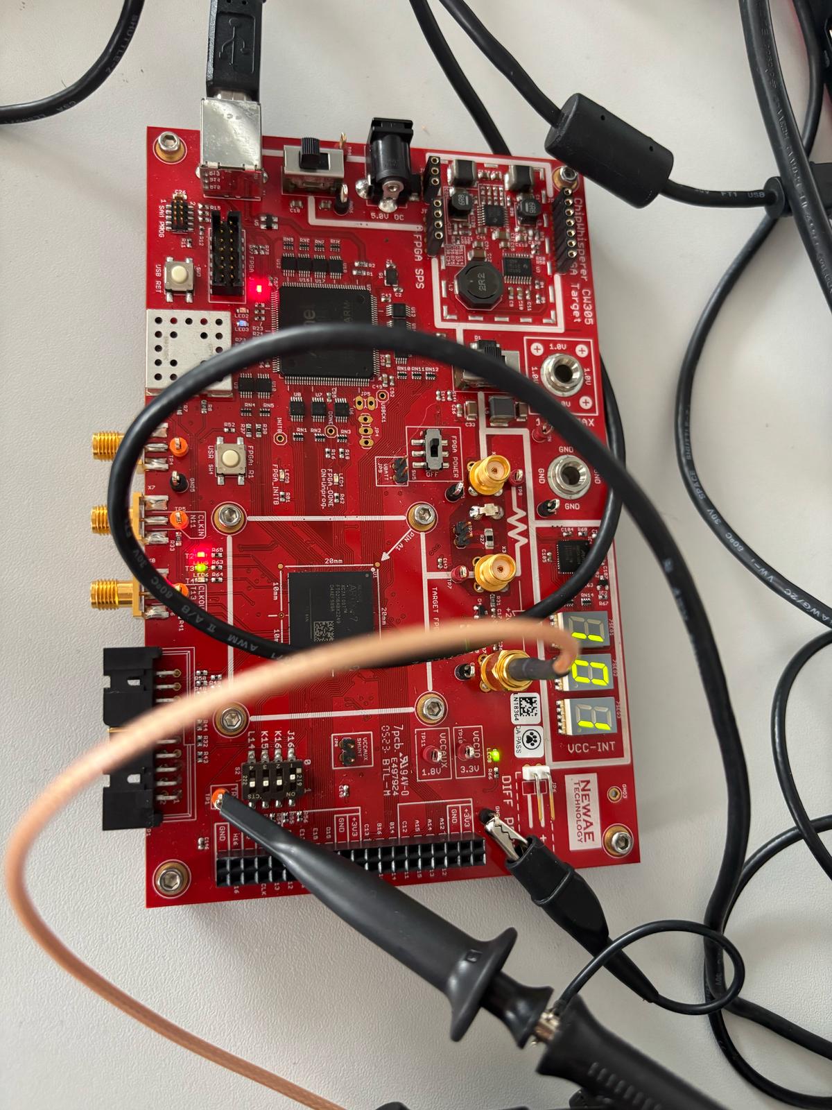
I’m working with a CW305 Artix‐7 board and attempting to measure an AES encryption. In the photos (attached), you can see my setup:
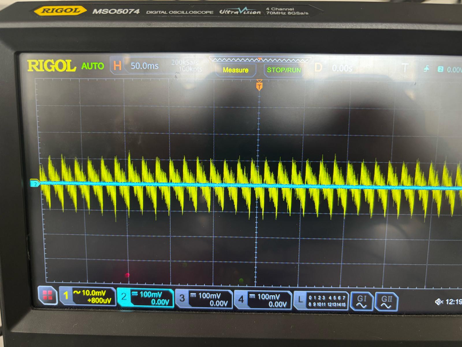
- Channel 1 (Yellow): Connected to the “x4” output on the CW305.
- Channel 2 (Blue): Connected to TP1, which, per the CW305 documentation, corresponds to the TIO4 pin (the “trigger”).
I’ve set my oscilloscope to 500 MSa/s. On Channel 1, I can see a signal of a few tens of millivolts in amplitude. However, on Channel 2 (the supposed trigger line), I’m only seeing what looks like noise at ~0 V, with no transitions at all.
To verify the trigger pin in hardware, I also put a voltmeter on TP1 while encryption was running. I expected some rise in voltage if the FPGA design was driving that pin, but the meter reads a constant 0 V. This suggests the line is never going high.
My questions:
- Is TIO4/TP1 definitely the correct location to measure the FPGA’s trigger signal on the CW305?
- Do I need to enable or map that TIO pin in my FPGA design constraints explicitly (e.g., set_property PACKAGE_PIN …)? I am using also the default bitstream.
- Why the trigger signal from TP1 is not rising during the encryption? I am sure that the encryption code is correct [I can provide the code if needed]
- How can I verify if the trigger is happening correctly so I can detected using the oscilloscope?
I suspect I’m either on the wrong pin or I haven’t properly driven that net in my FPGA code. But before I dive into constraints or board jumpers, I want to confirm I’m on the correct test point and that TIO4 is indeed the standard “trigger” connection.
Any guidance or tips would be greatly appreciated. Thanks!
Yes. It’s FPGA pin T14. Please refer to our example AES project to see how to do this: chipwhisperer/firmware/fpgas/aes/vivado at develop · newaetech/chipwhisperer · GitHub
Absolutely yes. Vivado won’t let you generate a bitfile if you don’t connect all of your top level ports to pins. But if you’re using our AES bitstream, this is all done.
There could be something wrong with your probe or oscilloscope setup. What is your oscilloscope triggering on? The trigger line goes high for about 1us; if your scope is not triggering its capture on it, then you will absolutely not be able to see it. Likewise, you will not be able to see the trigger with a voltmeter.
I’m confused: are you using our design or yours? I strongly suggest to first get your setup using our design, to eliminate one variable.
That’s not a wise approach: you should absolutely first verify that your constraints, pin assignments, and board jumpers are correctly set.
Then, if this is your design, the next step that I would take is to use ILAs to see why the target is not behaving as expected. Xilinx has lots of documentation to teach you how to do this. Good luck!
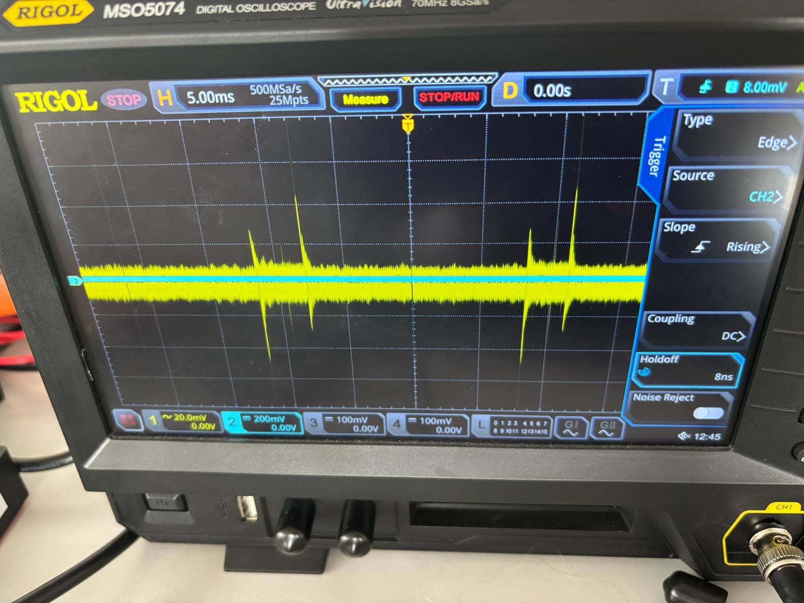
Yes, we are using the default bitstream (we are not using any custom design)as you can see in the code, and the oscilloscope trigger is on channel 2 which is connected to TP1, and the trigger settings are shown in the image attached. However, during the AES we should see a spike in the trigger and then it should go down when it finishes but this is not the case.
I’m not familiar with every oscilloscope model but it looks to me like your oscilloscope did trigger, which means there must have been a trigger pulse. If you don’t see it, maybe you need to zoom in, change your display scale, etc… As I said, it’s a very narrow pulse. The AES encryption is done in 10 clock cycles; it’s much faster than SW AES.
We already zoomed in but I don’t think it’s a problem of a pulse. Becaue one time after doing everyting and we run the bitstream not the ciphring code the trigger went up. But still we don’t understand why that happened and how.
Does “run the bitstream” mean programming the FPGA? The trigger output is driven by an FPGA pin; it’s not surprising that it should change levels when the FPGA is programmed.
I don’t know what else to add here; I think you are having problems operating your oscilloscope, and I can’t help you with that; try to find someone in your lab who can.
If you have ChipWhisperer capture hardware (i.e. CW-Lite, CW-Husky, or CW-Pro), then we can use that to verify that your CW305 is working correctly, and I can definitely help you with that. But I can’t help you with your oscilloscope.