phyWhisperer repair question - U4 replacement

Hello everyone,

I have recently damaged a phyWhisperer unit during voltage glitching experimentation.
As it turns out, the +5V high side power switches on the target USB line are not as robust as expected.

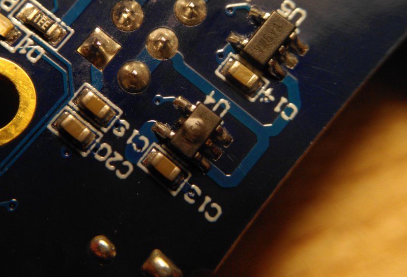
The broken part is U4:

The board is Rev 04A.

According to the official schematic, U4 and U5 are AP22802 devices, see sheet #7 in the schematic.

The Diodes Inc. AP22802 “single channel current-limited integrated high-side power switch” matches the description and pinout, and I’ve ordered some AP22802AW5-7 SOT-25 replacement parts after determining that the phyWhisperer needs the Active High = “A” variant.

After swapping the part with some SMD rework, the phyWhisperer target output generally works again in the basic sense that the target power can be switched between “off”, “host” (U4 active) and “5V” (U5 active) again.

However, the new U4 gets hot if the “+5V” source from the control interface is used (=U5 is supplying power, U4 is disabled).
I believe this is due to the built-in “Discharge Function” N-MOS in the AP22802 design that is draining power from the 5V line when the switch is disabled, effectively causing a sort of short for the power that U5 is supplying. This particular switch model is apparently not meant to be combined with other power sources.

I therefore suspect that the schematic is incorrect and that another chip is used which does not have the discharge functionality.

The original IC part is marked “VW 6y A”.
The AP22802 parts are marked “XA 1K B”, which is consistent with the “XA” identification code from its datasheet on page 12.

After some datasheet searching, I believe that the correct part would be the Diodes AP2171A, which is a SOT-25 part with the “VW” identification code. (Active High, 1 channel, 1.5A current limit, AP2171AW-7)

@coflynn, @Alex_Dewar: can you confirm that AP2171A is the correct chip?

Hi Invd,

Indeed - this was a “hardware hot patch”. We swapped the part for a AP2171AW based on a github issue (https://github.com/newaetech/phywhispererusb/issues/5). Boards after May/2020 had the new part (we swapped them on our assembled boards).

FWIW - we used that “wrong” part for a while before it came up (including internal stress tests). So following the schematic seems to “work” even if it’s a source of heat…

Due to supply chain issues the actual part also changes a little. I think the AP2191 was a possible sub (but not used). The actual max current isn’t normally needed here.

Also - I think you had a pending case/email I just remembered seeing this! I’ll respond there too and if you have trouble finding the part let us know, we can send you one (supply chain disasters etc).

Thanks,

-Colin

@coflynn:
I wasn’t aware of the Github issue, thanks!
I obviously recommend uploading an updated schematic so that other people don’t run into the same issue in the future.

Sourcing the AP2171AW-7 should not be a problem at the moment :+1: .

With regards to the current limit: given that I have managed to break the AP2171AW through the ChipWhisperer MOSFETs, I’ve been looking into switch variants with a lower current limit as an attempt at avoiding this by making the circuit more robust. Ideally, the current limit is adjustable down to maximum currents of ~0.5 A, so that it can be set depending on the target requirements without hardware changes.

The Diodes AP22615 looked interesting for this at first, but it is ruled out by the same problematic discharge behavior.

The best leads I’ve found so far were the

  • TI TPS2530 (fixed current limit at 1.0A ± 0.25A)
  • maxim MAX4995 series (0.05-0.6A current limit, need some special pin wiring)

At the moment, it looks easier to go with the standard AP2171A and add some external current limiting to the host voltage source.

Quick followup: I’ve now soldered in the “correct” AP2171AW replacement chip and everything works as expected.
The chip markings “VW 1L G” are slightly different since it is a different batch.

If anyone else runs into this issue, the Mouser part number for this is 621-AP2171AW-7.

I’ve written up this topic in more detail as a blog post.

@coflynn : the schematics has not been updated and still refers to the old, problematic AP22802, see sheet 7 of 8, top right. Is there a chance this can be fixed in the future?