Hello,
I’m trying to power trace the boot of a STM32F4 on VDD first and then VCORE. The MPU is in a LQFP64 socket with all VDD and VSS pins routed through a breadboard. 3.3V power is supplied by the CW313. nRST is connected to the CW313 and serves as the trigger. To measure the total power consumption I’ve placed a 10 Ohm resistor in series with the GND return, and SHUNTL/SHUNTH across it (based on this chipwhisperer-target-cw308t/CW308T_STM32F/CW308T_STM32F_02.PDF at main · newaetech/chipwhisperer-target-cw308t · GitHub ). That’s all that is plugged for now as I’m trying to keep things simple (so no CLK, no FILT).
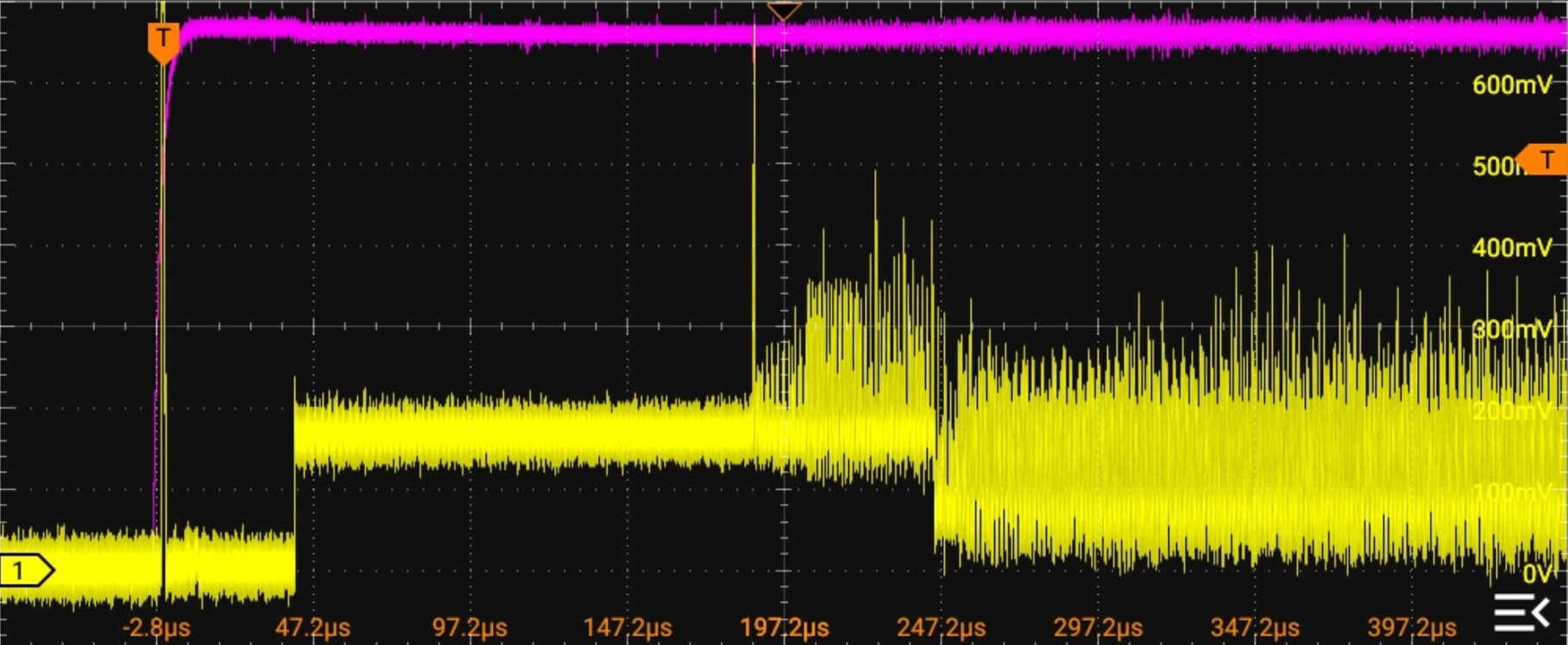
This oscilloscope trace shows the power consumption accross the resistor (yellow) with nRST (cyan) as the trigger:
My CW code:
%matplotlib widget
import chipwhisperer as cw
import time
import matplotlib.pyplot as plt
import numpy as np

scope = cw.scope()
scope.default_setup()

scope.gain.db          = 10
scope.adc.samples      = 100000
#scope.adc.presamples   = 10000
scope.adc.bits_per_sample = 8
scope.adc.clip_errors_disabled = True
scope.adc.lo_gain_errors_disabled = True
scope.adc.segments     = 1
scope.clock.adc_mul    = 4
#scope.adc.basic_mode   = "rising_edge"

# trigger on NRST
scope.trigger.sequencer_enabled = False
scope.trigger.triggers = "nrst"
scope.trigger.module   = "basic"
scope.io.nrst = "high_z"

def capture_boot_trace():
    scope.arm()
    scope.io.target_pwr = False
    time.sleep(0.5)
    scope.io.target_pwr = True

    ret = scope.capture()
    if ret:
        print("Capture timed out!")
        return None

    return scope.get_last_trace()

trace = capture_boot_trace()
print(f"Captured {len(trace)} samples")
print(scope.errors)

plt.figure(figsize=(14, 5))
adc_freq = scope.clock.adc_freq
x_us = np.arange(len(trace)) * (1e6 / adc_freq)
plt.plot(x_us, trace)
plt.title("STM32F4 Boot Power Trace")
plt.xlabel("us")
plt.ylabel("ADC amplitude")
plt.grid(True)
plt.tight_layout()
plt.show()
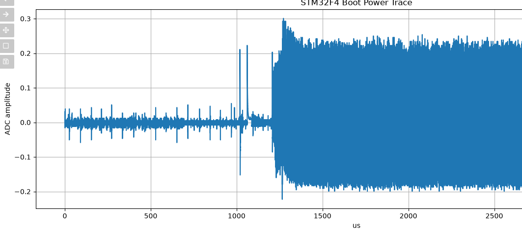
Produces this trace:
Same trace zoomed in a bit:
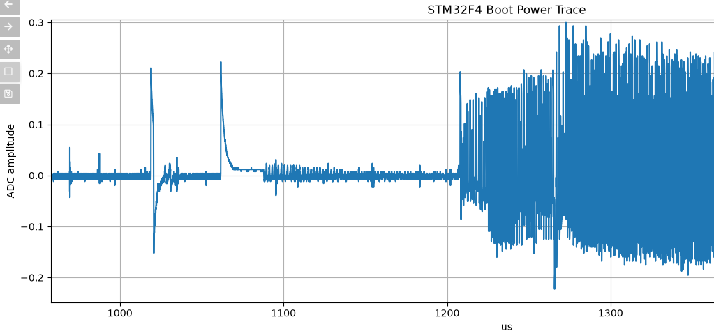
This looks nothing like what the scope says, I can’t reconcile the two traces. I get an ADC segmentation error which I think means there were several nRST triggers but I ignored them for now since a trace was pulled anyways. What am I doing wrong?