Question about Smartcard Acquisition

Dear Colin,

I am trying to perform acquisitions from a Java smartcard. My hardwareand softwaresetup is as per the linked tutorials.

I am trying to send a custom APDU self.hw.sendAPDU(0x00, 0xA4, 0x04, 0x00,[0xA0, 0x00, 0x00, 0x00, 0xFF, 0xF0, 0x01])

The console printout suggests that data is sent but none received. Do you have any advise regarding this? Thanks!

[code]APDU: 00 a4 04 00 07 a0 00 00 00 ff f0 01
ACK Error: a4 != a0
a0

Traceback (most recent call last):
File “C:\chipwhisperer-0.08\software\chipwhisperer\capture\ChipWhispererCapture.py”, line 714, in capture1
ac.doSingleReading()
File “c:\chipwhisperer-0.08\software\chipwhisperer\capture\AcquisitionController.py”, line 137, in doSingleReading
self.textout = self.TargetDoTrace(self.textin, self.key)
File “c:\chipwhisperer-0.08\software\chipwhisperer\capture\AcquisitionController.py”, line 91, in TargetDoTrace
self.target.go()
File “c:\chipwhisperer-0.08\software\chipwhisperer\capture\targets\SmartCard.py”, line 560, in go
self.protocol.go()
File “c:\chipwhisperer-0.08\software\chipwhisperer\capture\targets\SmartCard.py”, line 458, in go
status = self.hw.sendAPDU(0x00, 0xA4, 0x04, 0x00,[0xA0, 0x00, 0x00, 0x00, 0xFF, 0xF0, 0x01])
File “c:\chipwhisperer-0.08\software\chipwhisperer\capture\targets\SmartCard.py”, line 179, in sendAPDU
status = (p[-2] << 8) | p[-1]
IndexError: bytearray index out of range
[/code]

I forgot to mention that the same case applies for different APDU types. The smartcard has been tested to work on another system. Also, the ATMega on my victim board (and corresponding tutorials) work fine.

If I increase proctime in smartcard.py, I get a lot more data from temprx[], but these are not the expected response sent by the smartcard, but instead, repetitions of the original transmitted data.

Hello,

Are you using the smartcard hardware built into the ChipWhisperer I assume? I haven’t tested it extensively with ‘normal’ JavaCard type cards. It’s possible they are using unsupported protocols (different baud rates, etc). I mostly use the built-in reader for the MegaCard instead, which has a very fixed protocol specification! The built-in reader hardware doesn’t do any protocol negotiation, so it’s very basic.

To be honest most of the time I instead use a separate USB smartcard reader for interfacing to such cards, as the USB smartcard readers support almost everything, and are available for ~$30. Using the SASEBO-W interposer they can be connected up to the Multi-Target board, such that you can still perform power measurements or glitch insertion using the CW hardware. In addition this means you can use existing smartcard libraries to talk to the card, and don’t need to write everything form scratch.

I can provide some details on setting that up for you, I don’t think I have a demo of that…

Hi Colin, thanks for the reply.

Yes, I am using the Chipwhisperer capture rev2 and multi-target victim board to connect to a Java Card. Will continue to test and let you know!

Hi Colin,

The Java card does not respond because the RESET line is not toggled upon VCC supply. From the schematics of the Multi Target victim board , it seems that the smartcard RESET is not connected (except to the AT90usb162A if Jumper 8 is set).

I suppose a work around is to connect, in the FPGA, the ‘smartcard_rst’ to some unused FPGA outpin e.g. target_io1. And of course, to physically interconnect target_io1 and smarcart_reset on the victim board.

Is this a correct assumption or am I missing some thing crucial? Afterall, in the tutorial the SASEBO-W Card OS works perfectly with this setup; Does it not need a RST signal upon power?

Thanks and I look forward to your thoughts!

Some progress - Actually it isn’t too difficult to adapt the nice Verilog smartcard code from Colin’s Sasebo-W for the Capture Rev2 :slight_smile: 
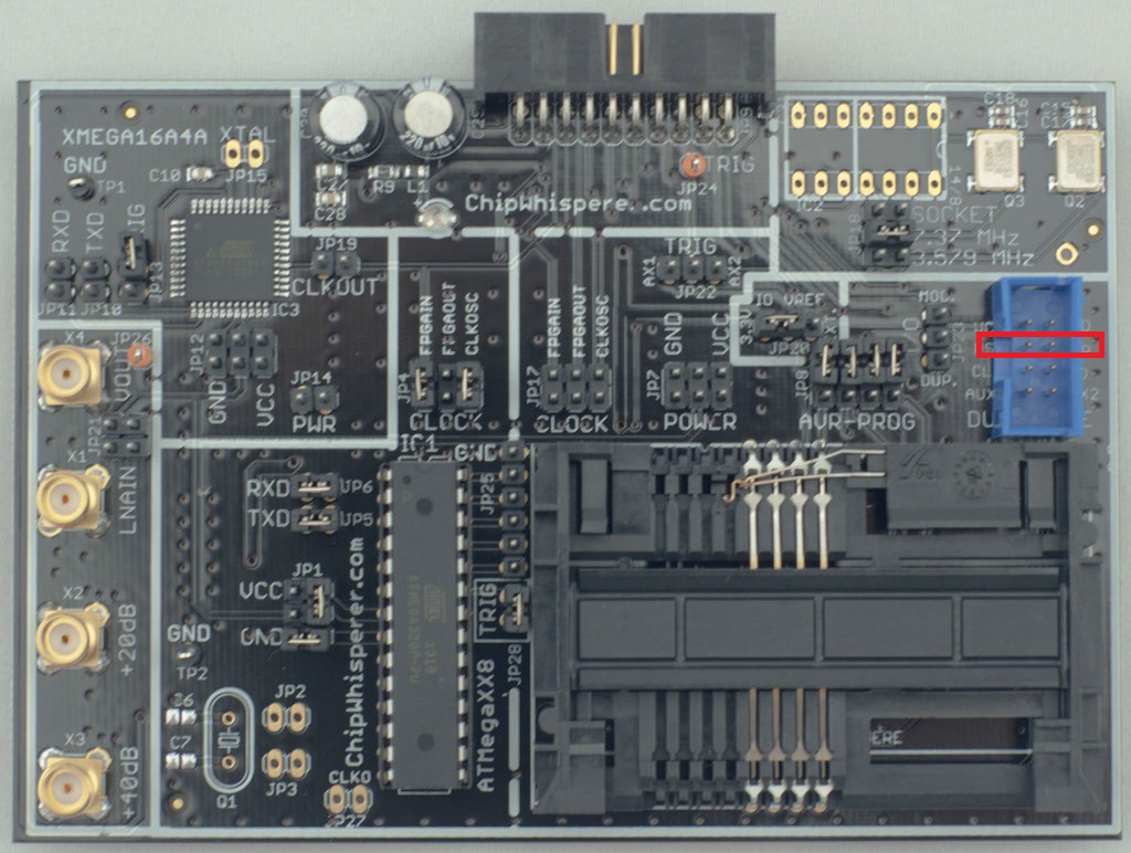
After that, you just need to route out the appropriate smartcard_rst signal from the Capture board to to JP16 on the Multi-target Victim board (via an extra soldered wire).

With an oscilloscope, I can observe the full 16 bytes ATR sent from the card.

However, it seems that only a single byte of the ATR is read by the Python software (each time reset() in CWSCardIntegrated is called). The subsequent ATR bytes are read by the Python oadc class which results in many errors thrown below. I’ll continue to debug this and update. Will also appreciate any insights from others

ERROR: ADVCLK register not present. Version mismatch (result[0]= 19)
Traceback (most recent call last):
  File "c:\chipwhisperer-0.08\openadc\controlsw\python\openadc\ExtendedParameter.py", line 73, in change
    linked.setValue(linked.opts['get']()) 
  File "c:\chipwhisperer-0.08\openadc\controlsw\python\openadc\openadc.py", line 735, in adcFrequency
    freq = freq | (temp[1] << 8);
IndexError: bytearray index out of range
ERROR: ADVCLK register not present. Version mismatch (result[0]= 10)
Timeout in read: 0
Traceback (most recent call last):
  File "c:\chipwhisperer-0.08\openadc\controlsw\python\openadc\ExtendedParameter.py", line 73, in change
    linked.setValue(linked.opts['get']()) 
  File "c:\chipwhisperer-0.08\openadc\controlsw\python\openadc\openadc.py", line 397, in extTriggerPin
    sets = self.oa.getStatus()
  File "c:\chipwhisperer-0.08\openadc\controlsw\python\openadc\openadc.py", line 901, in getStatus
    if len(result) == 1:
...

My setup (CW Capture Rev 2 + Multi-target victim board) now interfaces with javacards and I thought I’d share the process :slight_smile:

FPGA:

  • Both the Smartcard and the USI FPGA modules can be used to communicate with the smartcard. If like me, you are using the ztex_rev2_1.11c_ise, remember to uncomment the smartcard code appropriately. The limitation with the smartcard module is that the payload size is 16 bytes.
  • Route out the FPGA reset signal to an unused pin and physically connect it to the smartcard reset on the victim board (JP16)
    bb

Software/ Python
The reset signal in the original python code does not currently follow the ISO standard (it’s inverted). Simply invert the signal (This code interfaces with the FPGA smartcard module):

        cmd = bytearray(1)
        cmd[0] = 0x00;
        self.oa.sendMessage(CODE_WRITE, ADDR_STATUS, cmd, Validate=False)
        time.sleep(0.1)
        self.oa.flushInput()

        cmd[0] = FLAG_RESET;
        self.oa.sendMessage(CODE_WRITE, ADDR_STATUS, cmd, Validate=False)

Finally, some of the nitty-gritty ISO7816 details need to be implemented. For example, the card does not immediately respond with data to an APDU command, but instead with status word 61XY, where XY indicates the number of databytes response available. This must be obtained with the GET_RESPONSE command.

I hope this is helpful

First off - sorry I missed your earlier message from Nov 28, apparently my e-mail notification doesn’t always work from this forum. Anyway glad you were able to successfully get this to interface - longer term I’d like to implement a ‘better’ SCard driver from the FPGA, as it’s a bit of a hack-job right now.

But I’ll look to see if I could include the existing SCard code into the CWRev2 as well as the USI, they should both co-exist I think without any issue. There is some spare routing resources which would allow you to connect them up to the existing IO lines.

Hi Colin!

I just encountered a problem with sending a certain APDU type that results in the ‘busy’ flag of the smartcard status register staying high and the smartcard module becoming unresponsive.

So, to re-cap there are certain types of APDUs that work nicely. These are:
a. [CLA INS P1 P2] [ non zero payload ]
b. [CLA INS P1 P2] [ zero-size payload ] [ non-zero expected response length]

The APDU type which doesn’t work nicely is:
c. [CLA INS P1 P2] [ zero-size payload ] [zero expected response length] – > Card is expected to only respond with a status word.

I suspect that ap_ready never goes to high. The logic in smartcard.c looks fine and the case above should work, but I’ve yet to watch your Vivado HLS youtube video nor read into this topic in detail (debugging is for next week… :slight_smile:

Meanwhile, any comments / insights are appreciated! Thanks!

Best Regards
Alvin

Hmm… damn perhaps there is an error in the logic there! Have you seen the slightly newer module which just uses a standard serial-IO register?

I had mostly designed that system to work with the DPAContest v3 card, so I haven’t tested it with all possible card types. If you can use the newer register system it might be easier… the whole HLS system isn’t the most fun to install + debug! Although once you get it working it’s actually pretty cool.

Hi Colin, are you referring to reg_serialtarget.v?
The verilog code looks straightforward and fail safe :slight_smile:

I think it’s a great move which pushes more of the logic to the control sw (which is much simpler to write/debug)
gr8 job!

Yup - reg_serialtarget.v . Yes much more reasonable :wink:

The original reason for the complex smartcard interface is I had grand plans to have the SASEBO-W actually running the entire CPA attack in real-time on the FPGA. The idea being you could be attacking millions or billions of traces without having to store the data anywhere, and just getting the output results.

Ultimately it never happened… part of the reason being that the traces end up being a few GB, and storage is just so cheap. But I kept the convoluted smartcard interface until now!

So would that have been like an implementation of Pipeline Emissions Analysis?

While somewhat like a DSP implementation :wink:

My understanding of PEA is it uses the analog difference to drastically improve resolution - i.e. rather than storing a voltage of 1.00345V on one sample and 1.00356V on the next, it stores the difference of the two, which means your 10-bit ADC now only has to have a full-scale range of 10mV or whatever instead of the 2V range you might otherwise need. Doing it afterwards means you didn’t have as nice a resolution…

Actually my original plan was just a straight CPA attack. You can store the intermediate values as sums, although you’d need intermediate values for each sample point. So it’s not an insane amount of memory, but still a fairly large amount for a FPGA without using external memory (as the SASEBO-W doesn’t have any external memory on it).

Hi Alvin,

I am trying to replicate your setup. In the pic with the red highlighted box, is that jumper 16 smartcard reset?

Hi EbieJungle,

Yup, your red box covers two pins, make sure you connect it to the left pin (RST) and not the right (VPP)

Actually, Colin has already updated the smartcard tutorial on the chipwhisperer wiki, so it’s best to follow his solution :slight_smile:

Colin uses JP8 instead (doesn’t matter, the RST of JP8 and JP16 are shorted), but more cleverly, Colin controls the RST from GPIO1, so no FPGA code modifications need to be done. Furthermore, the latest CW Python software supports this setup.

Hi Alvin,

Thank you. I have followed the guide from Colin for the hardware setup. In the capture software reader hardware is set to ChipWhisperer-SCARD and when I send the command APDUSend it gives me the error APDUSend not defined. Additionally, when I set the reader hardware to ChipWhisperer-SER with the SASEBO-W SmartCard OS protocol, the software picks up the correct ATR. However, when using the command sendAPDU in the python console, I get the error sendAPDU not defined.

I just want to insert the javacard into the victim board, send the card an APDU and use to CW software to capture the power traces. If you or Colin could help, it would be greatly appreciated.

Regards.

Hey EbieJungle, perhaps you could post the full error log?

I would recommend ChipWhisperer-SER as it’s more stable and flexible than ChipWhispererSCARD. Anyway, receving the ATR is good news and means that your hardware setup is correct!

Hi Alvin,

Some logs:

OpenADC Found, ConnectingATR: 3b eb 00 00 81 31 20 45 4a 43 4f 50 33 31 33 36 47 44 54 78
ATR: 3b eb 00 00 81 31 20 45 4a 43 4f 50 33 31 33 36 47 44 54 78

self
<main.ChipWhispererCapture object at 0x06371328>
self.target.driver.ser
Traceback (most recent call last):
File “”, line 1, in
AttributeError: ‘SmartCard’ object has no attribute ‘ser’
self.target.driver
<chipwhisperer.capture.targets.SmartCard.SmartCard object at 0x0638A878>
self.hw.sendAPDU(0x80,0x01,0x05,0x03,0x00)
Traceback (most recent call last):
File “”, line 1, in
AttributeError: ‘ChipWhispererCapture’ object has no attribute ‘hw’
self.sendAPDU(0x80,0x01,0x05,0x03,0x00)
Traceback (most recent call last):
File “”, line 1, in
AttributeError: ‘ChipWhispererCapture’ object has no attribute ‘sendAPDU’
sendAPDU(0x80,0x01,0x05,0x03,0x00)
Traceback (most recent call last):
File “”, line 1, in
NameError: name ‘sendAPDU’ is not defined

When I click on Capture 1 this is the errors I get:

ACK Error: 12 != 0
ACK Error: not received?
Exception caught: Status too small: 0,
Traceback (most recent call last):
File “C:\chipwhisperer-0.10RC1\software\chipwhisperer\capture\ChipWhispererCapture.py”, line 786, in capture1
ac.doSingleReading()
File “c:\chipwhisperer-0.10rc1\software\chipwhisperer\capture\AcquisitionController.py”, line 141, in doSingleReading
self.textout = self.TargetDoTrace(self.textin, key=None)
File “c:\chipwhisperer-0.10rc1\software\chipwhisperer\capture\AcquisitionController.py”, line 91, in TargetDoTrace
self.target.go()
File “c:\chipwhisperer-0.10rc1\software\chipwhisperer\capture\targets\SmartCard.py”, line 805, in go
self.protocol.go()
File “c:\chipwhisperer-0.10rc1\software\chipwhisperer\capture\targets\SmartCard.py”, line 594, in go
status = self.hw.sendAPDU(0x80, 0x04, 0x04, 0x00, self.input)
File “c:\chipwhisperer-0.10rc1\software\chipwhisperer\capture\targets\SmartCard.py”, line 193, in sendAPDU
raise IOError(“Status too small: %d, %s” % (len(stat), " “.join([”%02x"%ord(t) for t in stat])))
IOError: Status too small: 0,

Edit

By looking at the SmartCard,py my understanding is that I have to add my own template or modify one of the existing templates to send the APDU to the smartcard?

You are correct, when you click Capture1, it calls the ‘go’ function of the selected Protocol e.g. SASEBOcardOS . The main code changes you need to make are here in the protocol class where you define the logical APDUs appropriate for your smartcard (e.g. select AID, the command for encryption, sending PT and receiving CT). Colin’s ProtocolDPAv42 provides a good reference.

The protocol class sends this to the reader you selected (e.g. Chipwhisperer-SER) which defines the lower level communication stuff. You shouldn’t need to edit anything here unless you change the Verilog…

Some potentially bad news, from your ATR, your smart card uses the T1 protocol (see ISO7816), which is a bit more verbose than the T0 protocol in ProtocolDPAv42.

It’s a bit more work but still manageable if you know exactly what bytes are written in each communication run which should be pretty static.