Hi Everyone,
I have a question on modifying the NXP LPC1114 target for Tutorial A9.
To allow the ChipWhisperer-Lite to interface with this board, we’ll need to make some small modifications to the board:
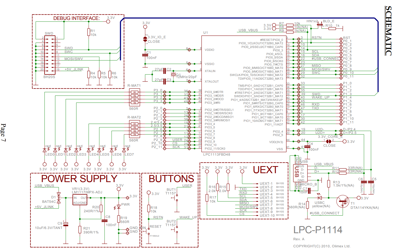
4. Cut the traces on 3.3V_CORE and 3.3V_IO_E.
5. Add a 12-ohm resistor on the 3.3V_CORE jumper.
In Step 4, I interpreted the cutting of both traces (see below) as a mean to disconnect the 3.3v power supply to the chip, and subsequently providing power via the SMA glitch port of the Chipwhisperer.
If my interpretation is correct, what is then the purpose for adding the 12-ohm resistor in Step 5?
By adding back a 12-ohm resistor, the chip then draws power back from the 3.3v power supply. Will we then still be able to voltage glitch it?
I also noticed on Dmitry’s blog series that he did not use a resistor across the 3.3V_CORE jumper. Instead, he supplied glitch power directly to both 3.3V_CORE and 3.3V_IO_E jumpers. Any idea why is this so?
Thanks.
Regards,
Melvin.
Hi Melvin,
The purpose of the 12ohm resistor is to increase the impedance between the 3.3V rail and the power pins of the chip, making it easier for the glitch module on the ChipWhisperer to drop the voltage at the power pins (similar idea with removing the decoupling capacitors). The glitch port on the ChipWhisperer is actually an open drain setup, so it can’t supply power to the circuit, only drop it to ground (as can be seen by the schematic for the ChipWhipserer Lite: https://github.com/newaetech/chipwhisperer/blob/master/hardware/capture/chipwhisperer-lite/pcb/cw-lite-main.pdf).
Alex
Hi Alex,
Thanks for the explanation.
How do you derive the value of this resistor to be 12-ohm?
Must the resistor value be 12-ohm? I could only find a 10-ohm 0603 resistor salvaged from other devices. Will this 10-ohm resistor work?
Does this value vary from one target to another, say the LPC1343 in Dmitry’s blog series?
Regards,
Melvin.
Hi Melvin,
The 12-ohm value is entirely random (1 ohm seems too small, 1K seems too high). 10 ohms is def OK - there is really to specific value needed here. Instead it just allows the ChipWhisperer to short the VCC supply without as much ringing etc.
The value should work pretty well on other targets!
The other point of the resistor is it also allows you to do nicer DPA measurements, so you can observe the boot sequence.
Warm Regards,
-Colin
Hi Colin,
Thanks for the explanation. Just a few more questions.
I was trying to repeat the following steps but the output I got from the target doesn’t seem to match:
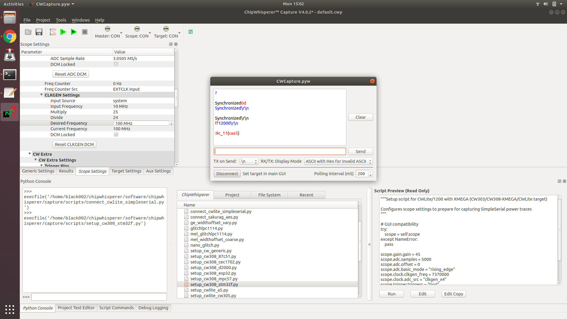
Before we can do any read operations, we’ll need to properly initialize the bootloader. Note that the bootloader will echo back what is sent to it by default.
- Reset the device. This can be done by pulling the RST pin low from the CW Capture, or by pressing the RESET button on the dev board/CW308.
- Send a “?” to the device. It will use this to detect the baud rate. From now on, all messages should be terminated by “\r\n”.
- The device will send “Synchronize\r\n”.
- Respond with “Synchronize\r\n”. The device will respond with “OK\r\n”, though it will probably be “Synchronize\rOK\r\n” due to the echo.
- Send the frequency of the external clock in KHz. The dev board uses a 12MHz clock, so we should respond with “12000\r\n”.
- The device will respond with “12000\rOK\r\n”.
Any idea what may be missing here?
Also, how should I go about configuring the LPC1114 to CRP1? Flash Magic or LPCXpresso?
Thanks.
Regards,
Melvin.
Hi Melvin,
I’d recommend trying TX on Send instead of specifying the line termination in the terminal, since the terminal might be sending '\' + 'r' and '\' + 'n'.
If I recall correctly, you just need to write the CRP value you want to the correct location in flash, so anything that lets you do that should work (I’m pretty sure we used a debugger to write to that location). My guess is Flash Magic will work fine.
Alex
Hi Melvin,
As a quick note too - in the new CW5 that tutorial was extended considerably. This includes the ability to set the fuse bytes directly over the bootloader, see https://github.com/newaetech/chipwhisperer-jupyter/blob/master/Fault_6-LPC1114_Fuse_Bypass.ipynb for an onverview.
-Colin
Hi Alex and Colin,
Thanks for the replies. I really appreciate them.
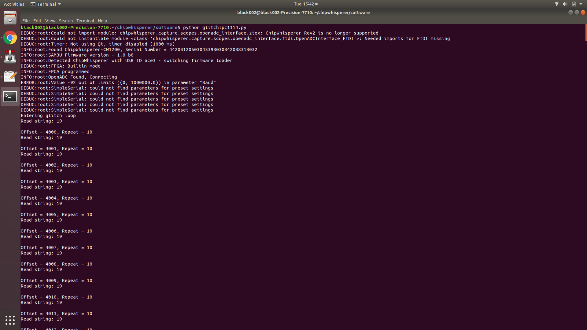
I just need a little more help. I have modified the LPC board (mine is a LPC1343) and used the “Method 2” script here to perform the voltage glitching. I have been running that script for days and trying different external glitch offset and repeats. None of the combinations I tried seem to work. I also noticed that some weird debug messages at the start of the python script.
I am not sure if those debug messages affect the voltage glitching capabilities of the Chipwhisperer Pro. What did work was with CRP disabled, the python script could dump out the contents of the flash.
Any suggestion? Should I try using other glitch widths and offsets (currently those are 40 and 10, respectively)? Also, is it possible to share some sample firmware of the LPC1114 with CRP1 enabled and CRP disabled? Thanks.
Regards,
Melvin.
Hi Melvin,
The baud error you’re seeing there was a bug involving the first read of the baud setting for the IO trigger on the pro. On the hardware side, the value was uninitialized on startup, meaning this first read could trigger could be out of the software side limits. It’s really only a visual bug though, since the value is initialized right after the first read. This bug was fixed for the CW5 release. None of the error messages should affect voltage glitching.
The attack itself uses the enable_only glitch output, meaning the glitch port is pulled low for a full clock cycle (1/200MHz by default). The glitch width and offset parameters won’t have any effect in this mode, since they control where and how long a glitch is placed within a clock cycle. Using enable_only as in this tutorial, with a clock speed much higher than the target, effectively replaces width and offset by repeat and ext_offset, respectively.
Voltage glitching can vary a lot with small hardware differences, so you may have to expand the glitch range a bit, in particular the repeat value. Also, if you’ve got an oscilloscope on hand, try taking a look at the glitches on it to make sure they’re going through properly.
Regarding firmware, I don’t believe we really built anything for the board beyond a basic binary to upload onto the board. I’m not sure if we’ve got any of that stuff lying around anymore, but I’ll see if I can find it for you.
Alex
Hi Alex,
A basic binary for the board is more than sufficient =)
Anyways, I tried expanding the external glitch offset (10000-11999) and repeats (10-39).
I also added a few lines of code to have 3 attempts for each pair of glitch parameters.
I’m seeing some “unexpected error code” (which I assume is a good sign) under 13 repeats and nothing beyond that. GlitchResults2105_0200.zip (195.7 KB)
I have also tried using high power glitch, i.e scope.io.glitch_hp = True, but I’m not getting any success as well. By the way, what is the difference between low and high power glitch? I could only find the glitch_hp description at the readthedocs.
Is there anything else I can try? Does changing the shunt resistor value (currently it is 12 ohms) help?
Thanks.
Regards,
Melvin.
Hi Melvin,
I’ve attached the binary for the lpc1114. Not sure what it does, but it should at least be valid code:
lpc1114_board.zip (5.2 KB)
I’d guess that the “unexpected error code” probably is a good sign, since you’re at least having an effect on the target. What might be happening here is that the larger glitches are causing the target to reset.
The difference between the high power and low power glitch is which FET is used to drop Vcc to ground. The high power glitch FET is the IRF7807ZTRPBF (U8 on the front side of the board), while the low power glitch FET can vary based on when the ChipWhisperer was assembled (T4 on the bottom side of the board). The high power glitch might be a good avenue to look into here. The offset shouldn’t need to change substantially, but the repeat value might need to be a bit different (either higher or lower).
Changing the shunt resistor value might help, but it also might not. I’d check into using the high power glitch before changing the shunt resistor.
Alex
Hi Alex,
I have tried both the high and low power glitch options and ran them through millions of iterations. Sadly, no luck still T__T
Anyways, if I were to replace the shunt resistor, I should be using one with a higher resistance right, say 20 ohms or 100 ohms?
Regards,
Melvin.
Hi Melvin,
It’s worth a try, but you might also want to try decreasing the value of the shunt resistor as well (just be a little careful with how much you decrease the shunt value). Oftentimes, a glitch that rings a lot can work better than one that doesn’t.
Alex
Hi Alex,
It’s been awhile. After swapping a number of resistors, I finally managed to glitch the LPC1343 bootloader to bypass CRP1. Seems that the 23-ohm resistor worked best for me.
Thanks again for all the suggestions and help =)
Regards,
Melvin.
2 Likes