No. To cut down on the back-and-forth, carefully follow the instructions below.
First, let’s define our switches:
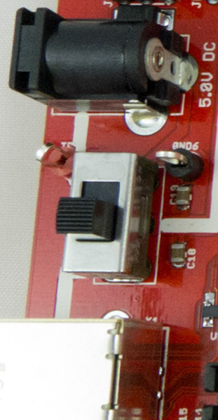
- switch 1, power supply: next to the USB jack (picture)
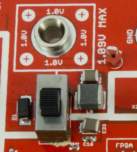
- switch 2, external supply: next to the banana jacks (picture)
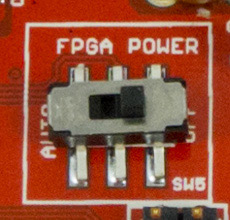
- switch 3, FPGA power (picture)
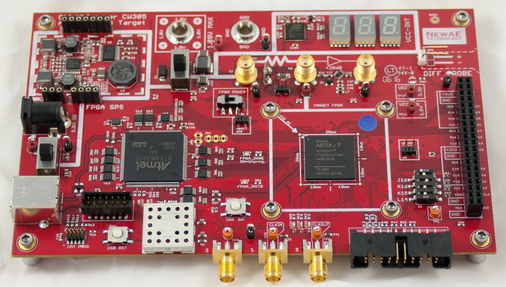
- Orient the board so that the USB and DC jacks are on the left-hand side (like this).
- Always keep switch 3 to its left-most position.
- Always keep switch 2 to its down position.
- Connect a USB cable and put switch 1 in its down position.
(a) What is the status of all LEDs?
(b) If the LCD display does not show 1.00, try a different USB cable, then a different USB port, then a different computer. - If (3) doesn’t work, power the board from the 5V DC jack. Set switch 1 to the up position. What is the status of all the LEDs?