SAD ADC multiple segmented trigger does not match the count of triggers seen - segmenting error ("02 - Husky Triggers" demo)

Ultrashort TL;DR summary

I am always getting error ADC errors = segmenting error, mismatch in scope.SAD.num_triggers_seen == scope.adc.segments, there is an assert on it in 02 - Husky Triggers.ipynb under the “SAD Triggering section” no matter what parameters I set up:

assert scope.SAD.num_triggers_seen == scope.adc.segments

Summary continued

I tried to experiment with scope.adc.gain from 16 to 20 to avoid “gain too low”, currently at 18 which looks good for everything else. Changed around scope.adc.samples to lower (90, 300, 600), tried to change scope.SAD.threshold to 80 or 90 (or even 1000 just to get feel what the results will be).

If triggers seen is less than scope.adc.segments, then I get FIFO errors as well, sometimes presample error when I made the params way out of bound.

I wasn’t able to find out the correct params to make that assert valid, go through SAD multiple capture trigger without any error, and there’s too many of parameters.

I’ve already spent 3 days looking through the data and docs, but still don’t have very good idea at what I am doing wrong. I don’t know what I am looking for since there is no example data in some screenshot (or pickled…) to compare to mine to to know that I am off way to the moon with parameters of mine.

(I always powercycle everything and kill jupyter server between each experiment to know we’re starting freshy fresh.)

My setup

  • Notebook: 02 - Husky Triggers.ipynb (I only added print scope.errors or scope.errors.clear() while experimenting, aside from changing around paremeters as described above)
  • Setup: CW Husky + CW308 UFO board + STM32F303 target
  • CW version: commit 534fe4881bb54723eb43df465cc54b406d9ccc4f from Mar 20 2023 (later than 5.7.0) on Linux

Segmentation error

I will first show the few triggers that are working so that we/you can see if it’s right, seems right to me, but I don’t have much to compare to.

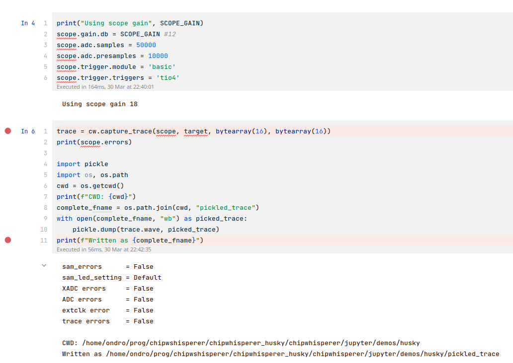
ADC and SAD first look and work OK until I get to the multiple segment part

So basically starting 02 - Husky Triggers.ipynb, I just run the first 4 cells to acquire CW scope, program and reset STM32F303 target.

Then I continue onto “2. ADC level triggering” part

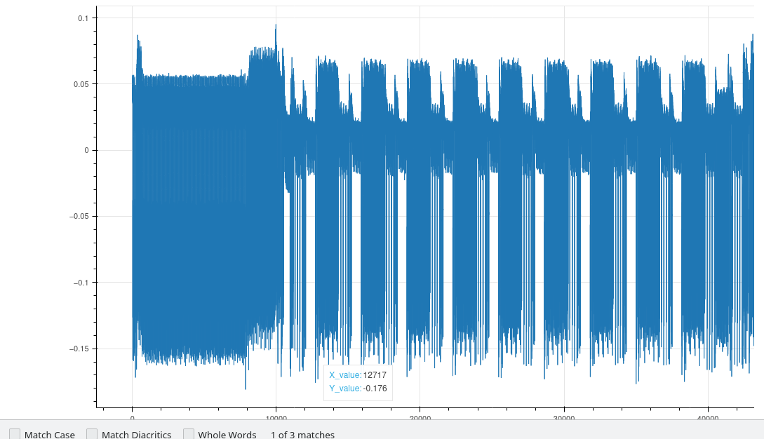
So this kinda looks reasonable as the first trigger graph (from TIO4 IIRC?), right? 10 round of AES, plus one extra for initial key addition (vanilla hardware/victims/firmware/simpleserial-aes/simpleserial-aes-CW308_STM32F3.hex demo, compiled without any modifications).

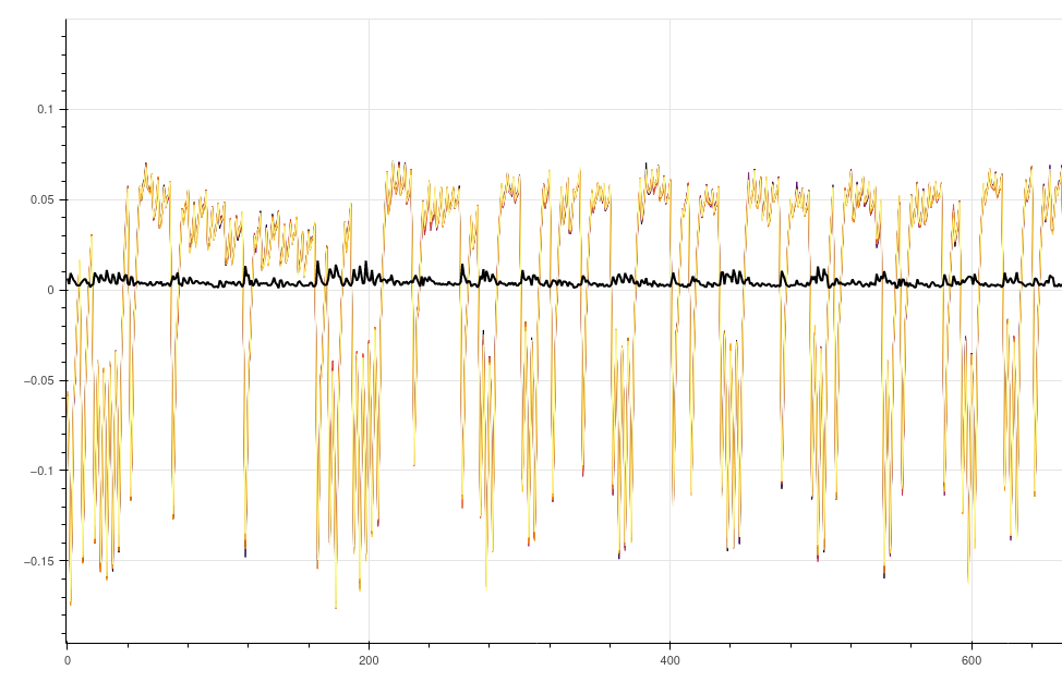
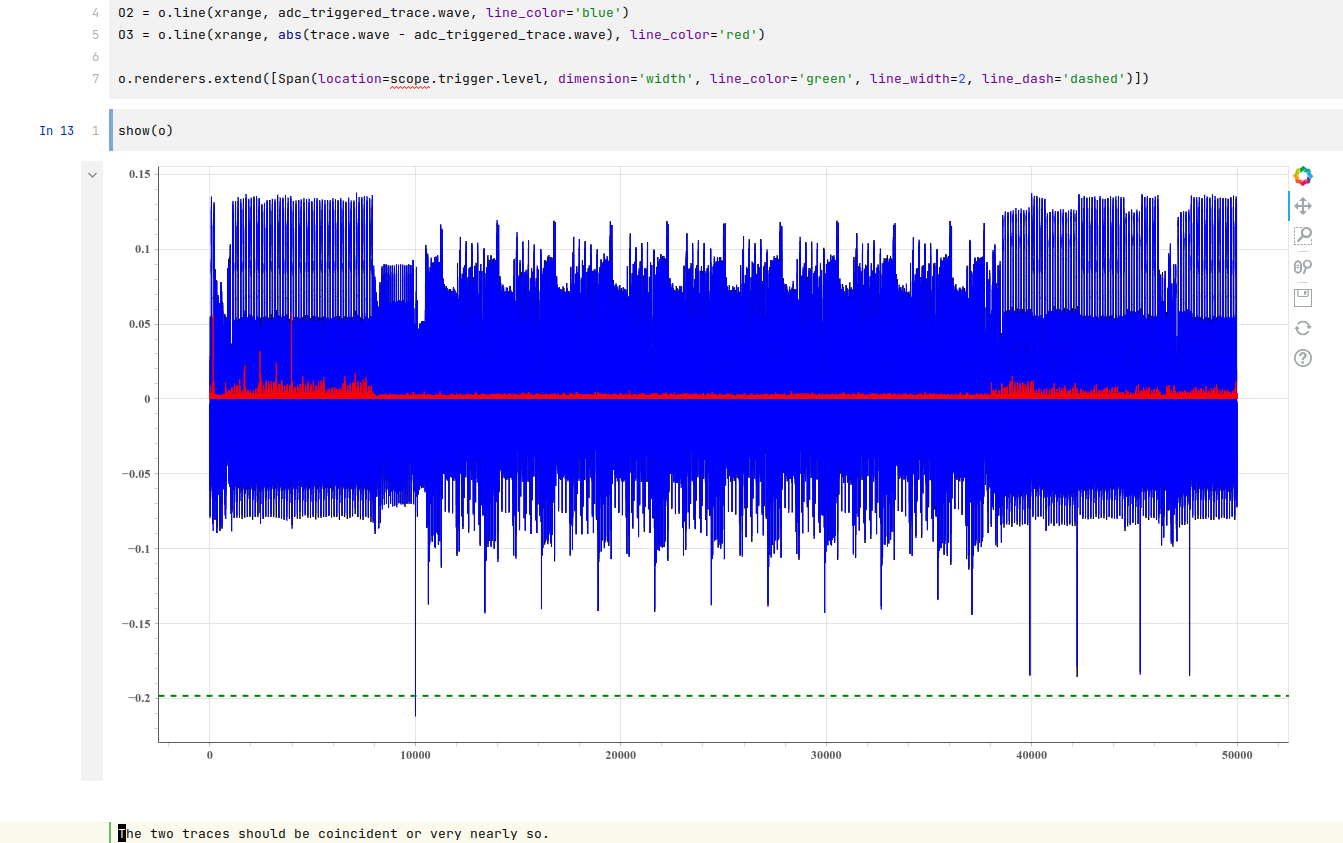
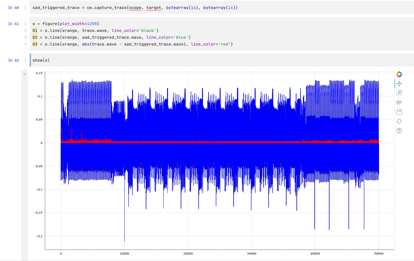
Second graph where we see the absolute difference in red on ADC trigger, which looks OK:

First SAD trigger in demo looks also right:

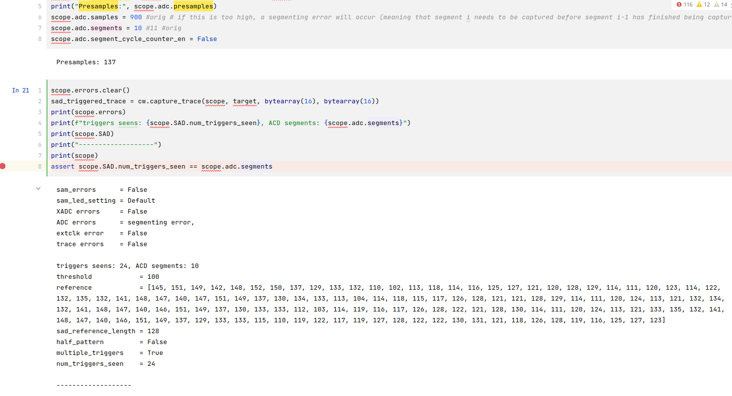
Now here is when we run in trouble with the SAD multiple triggers

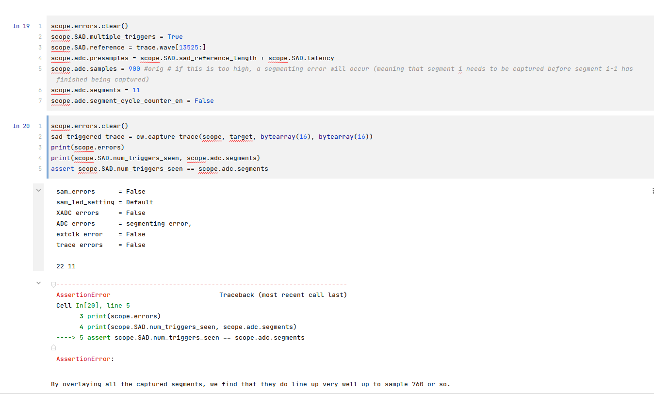
Here I always get some error, segmenting error is the most common, no matter how I tune the variables (mentioned at the beginning like gain, samples, threshold…). I am lost at this point.

I always either get more scope.SAD.num_triggers_seen than scope.adc.segments otherwise FIFO or other error will happen.

Is the assert right though? Must it be exactly the same? It’d make more sense to allow more triggers seen than segments maybe?

Documentation for segmenting error:

the condition for starting the capture of the next segment came true before the capture of the current segment completed. Reduce the segment size and/or increase the time between segments.

I can’t figure out what to change to make it right.

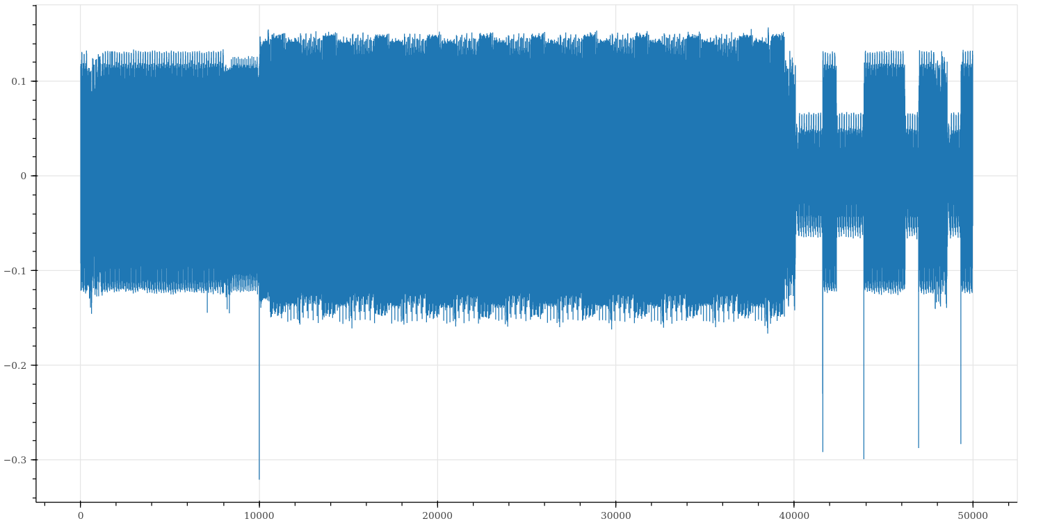
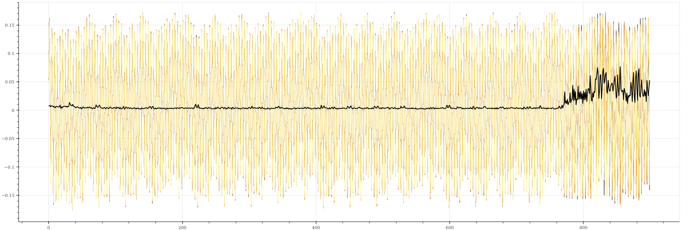
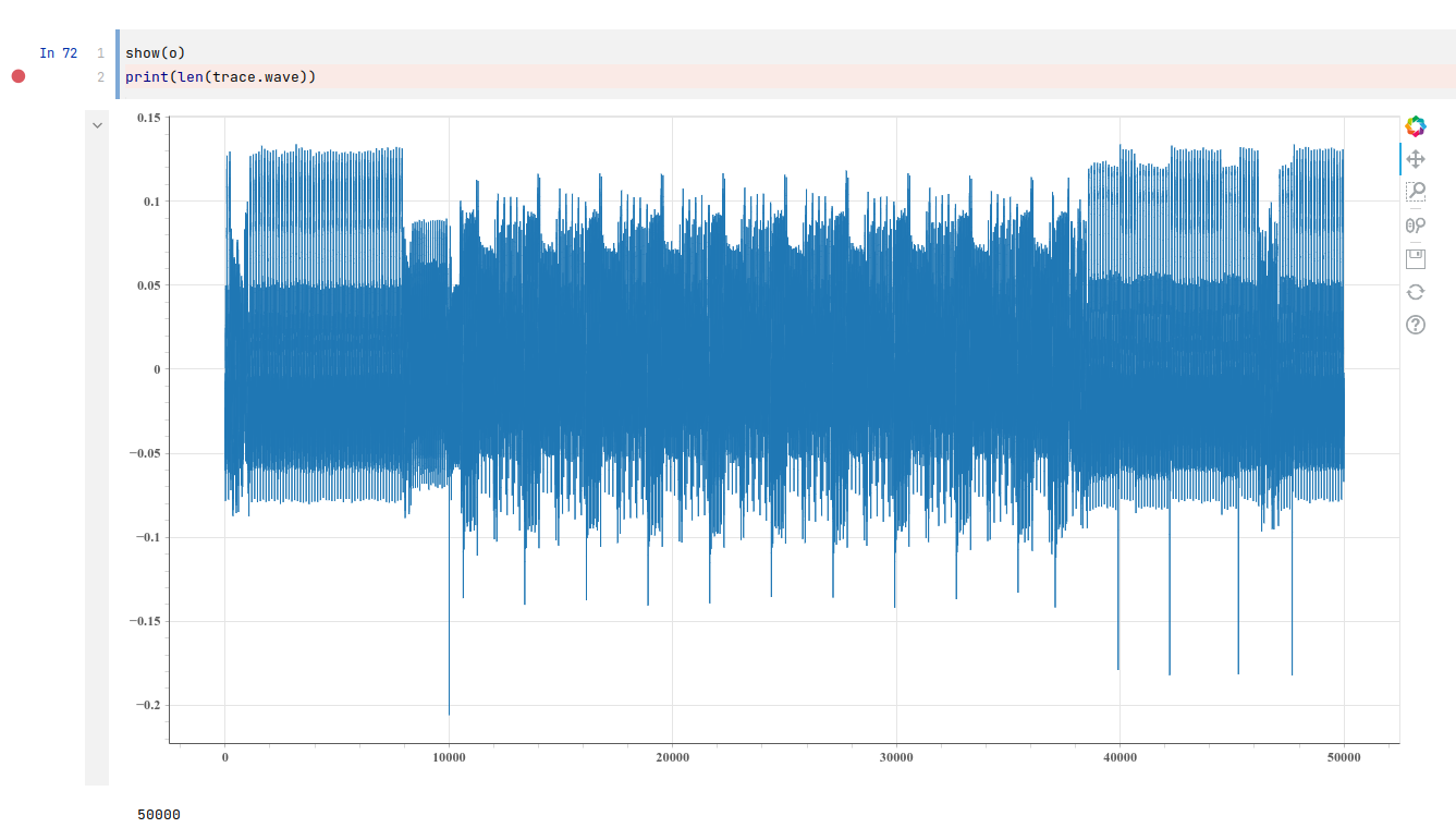
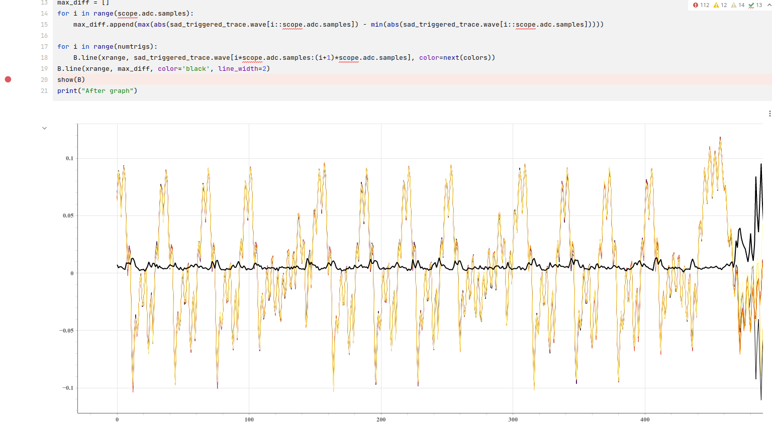
Then just for the fun of it I let generate it graph from the data which I am not sure if it means anything useful, but just for reference:

Thanks for reading this, I’ve been writing this report for a few days.

Thanks for the detailed report! At the root of this is that despite using the same target (and same firmware, presumably?) your traces look a bit different from mine:

That should not prevent SAD triggering from working in your case. But some of the things that you tried will definitely not work:

  1. gain: choose a gain that gives you a reasonable dynamic range, and then don’t touch it! SAD will not work well if the gain for your SAD-triggered trace is different from that of your reference trace.
  2. samples: one thing that may not be obvious is that scope.adc.samples must be larger than scope.adc.presamples (as documented here) , otherwise you will get a segmenting error.
  3. threshold: using a very high value when scope.SAD.multiple_triggers = True will very likely result in segmenting errors.

In case it’s not clear, a segmenting error is when the triggering event for capturing the next segment occurs before the previous segment is done being captured (or when presamples > samples). If the SAD threshold is so high that the SAD trigger can fire all the time (e.g. more often than it should), then you are pretty likely to run into this.

What we’re trying to do here is to use multiple SAD triggers to capture each AES round separately as a trace segment. Your final plot looks quite reasonable: you have traces that overlap very closely for what looks like the duration of an AES round, and then diverge. For reference this is what I get:

If you try again, keeping in mind the advice above on setting gain/samples/threshold, and the scope.SAD.num_triggers_seen == scope.adc.segments assertion still fails, what is the output of scope.SAD?

No, if the SAD and capture parameters are properly set, then they should be exactly the same. scope.adc.segments is how many SAD triggers you’re expecting to get and scope.SAD.num_triggers_seen is how many SAD triggers you actually get.

One thing you could try is to reduce scope.adc.segments to 10 instead of 11; it may be that if you used a different compiler/version to generate the firmware, your power trace does not segment nicely into 11 “rounds” like mine does.

I hope this helps,
Jean-Pierre

gain: choose a gain that gives you a reasonable dynamic range, and then don’t touch it! SAD will not work well if the gain for your SAD-triggered trace is different from that of your reference trace.

Currently I always set SCOPE_GAIN at beginning, been using 18 for a long time, print it (for check) and set it every time it’s set it any part scope.adc.gain setting anywhere in the example to avoid hand-editing the number on each line where scope.adc.gain is set. I think the gain 18 looks OK from the previous screenshots?

Maybe I should’ve been clearer it was more experimenting that I tried each combination of those completing from start to finish (including power cycle, restart jupyter notebook and go start to end), like in this pseudo-code (so bunch of runs) :

for gain in [16, 18, 20]:
    for scope.adc.samples in [90, 300, 600]:
        for scope.SAD.threshold in [80, 90, 100, 1000]:
            run the wole experiment from start to end, powercycle husky, restart jupyter each time

samples: one thing that may not be obvious is that scope.adc.samples must be larger than scope.adc.presamples (as documented here) , otherwise you will get a segmenting error

I understand that part now, so I added a print to check so the above holds (so scope.adc.presamples is 137, less than scope.adc.samples 300 or 600 - or 900 which is in original notebook):

print("Presamples:", scope.adc.presamples)
137

Like following screenshort from the part that fails the assert:

  • prints errors
  • prints triggers seen vs scope segment (triggers is 24, segments is 10)
  • prints scope.SAD
  • prints finally scope (will add scope.SAD and scope output extra as text to be easier to read

scope.SAD printout

threshold            = 100
reference            = [145, 151, 149, 142, 148, 152, 150, 137, 129, 133, 132, 110, 102, 113, 118, 114, 116, 125, 127, 121, 120, 128, 129, 114, 111, 120, 123, 114, 122, 132, 135, 132, 141, 148, 147, 140, 147, 151, 149, 137, 130, 134, 133, 113, 104, 114, 118, 115, 117, 126, 128, 121, 121, 128, 129, 114, 111, 120, 124, 113, 121, 132, 134, 132, 141, 148, 147, 140, 146, 151, 149, 137, 130, 133, 133, 112, 103, 114, 119, 116, 117, 126, 128, 122, 121, 128, 130, 114, 111, 120, 124, 113, 121, 133, 135, 132, 141, 148, 147, 140, 146, 151, 149, 137, 129, 133, 133, 115, 110, 119, 122, 117, 119, 127, 128, 122, 122, 130, 131, 121, 118, 126, 128, 119, 116, 125, 127, 123]
sad_reference_length = 128
half_pattern         = False
multiple_triggers    = True
num_triggers_seen    = 24

scope printout

cwhusky Device
sn             = 50203120374a38503230343138303037
fpga_buildtime = 3/2/2023, 21:35
fw_version = 
    major = 1
    minor = 5
    debug = 0
gain = 
    mode = high
    gain = 7
    db   = 18.211009174311926
adc = 
    state                    = False
    basic_mode               = rising_edge
    timeout                  = 2
    offset                   = 0
    presamples               = 137
    samples                  = 900
    decimate                 = 1
    trig_count               = 24
    stream_mode              = False
    test_mode                = False
    bits_per_sample          = 12
    segments                 = 10
    segment_cycles           = 0
    segment_cycle_counter_en = False
    clip_errors_disabled     = False
    lo_gain_errors_disabled  = False
    errors                   = segmenting error, 
clock = 
    clkgen_src             = system
    clkgen_freq            = 7370129.87012987
    adc_mul                = 4
    adc_freq               = 29480519.48051948
    freq_ctr               = 57
    freq_ctr_src           = extclk
    clkgen_locked          = True
    adc_phase              = 0
    extclk_monitor_enabled = False
    extclk_error           = False
    extclk_tolerance       = 102.996826171875
trigger = 
    module = SAD
io = 
    tio1            = serial_rx
    tio2            = serial_tx
    tio3            = high_z
    tio4            = high_z
    pdid            = high_z
    pdic            = high_z
    nrst            = high_z
    glitch_hp       = False
    glitch_lp       = False
    extclk_src      = hs1
    hs2             = clkgen
    target_pwr      = True
    tio_states      = (1, 1, 1, 0)
    cdc_settings    = bytearray(b'\x00\x00\x00\x00')
    aux_io_mcx      = high_z
    glitch_trig_mcx = trigger
glitch = 
    enabled           = False
    mmcm_locked       = False
    num_glitches      = 1
    clk_src           = target
    width             = 0
    offset            = 0
    trigger_src       = manual
    arm_timing        = after_scope
    ext_offset        = 0
    repeat            = 1
    output            = clock_xor
    phase_shift_steps = 4592
ADS4128 = 
    mode      = normal
    low_speed = True
    hi_perf   = 2
LA = 
    present                  = True
    enabled                  = False
    clkgen_enabled           = False
    locked                   = False
    clk_source               = pll
    trigger_source           = glitch
    oversampling_factor      = 1
    sampling_clock_frequency = 0.0
    downsample               = 1
    capture_group            = glitch
    capture_depth            = 0
trace = 
    present      = True
    enabled      = False
    errors       = False
    trace_synced = False
    trace_mode   = parallel
    trace_width  = 4
    clock = 
        fe_clock_alive   = True
        fe_clock_src     = usb_clock
        clkgen_enabled   = False
        fe_freq          = 96000000.0
        swo_clock_locked = False
        swo_clock_freq   = 0.0
    capture = 
        trigger_source         = firmware trigger
        use_husky_arm          = False
        raw                    = True
        rules_enabled          = []
        rules                  = []
        mode                   = while_trig
        count                  = 0
        max_triggers           = 1
        triggers_generated     = 1
        record_syncs           = False
        matched_pattern_data   = 0000000000000000
        matched_pattern_counts = [0, 0, 0, 0, 0, 0, 0, 0]
XADC = 
    status                               = good
    current temperature [C]              = 48.5
    maximum temperature [C]              = 50.6
    user temperature alarm trigger [C]   = 80.0
    user temperature reset trigger [C]   = 59.9
    device temperature alarm trigger [C] = 89.9
    device temperature reset trigger [C] = 59.9
    vccint                               = 0.998
    vccaux                               = 1.797
    vccbram                              = 0.997
userio = 
    mode       = normal
    direction  = 0
    drive_data = 0
    status     = 511
LEDs = 
    setting = 0 (default, as labelled)
errors = 
    sam_errors      = False
    sam_led_setting = Default
    XADC errors     = False
    ADC errors      = segmenting error, 
    extclk error    = False
    trace errors    = False

One thing you could try is to reduce scope.adc.segments to 10 instead of 11; it may be that if you used a different compiler/version to generate the firmware, your power trace does not segment nicely into 11 “rounds” like mine does.

I did reduce to adc.segments to 10 as you suggested, still getting many more triggers (>20 usually, more than 10 expected).

My trace looks a lot more “spikey”, so sum of differences will be different probably compared to your trace I guess.

My guess is the answer lies somewhere in this segmenting error description that I should modify the SAD threshold probably, but I have hard time debugging because I don’t see where exactly the overlap happened:

the condition for starting the capture of the next segment came true before the capture of the current segment completed. Reduce the segment size and/or increase the time between segments.

Any way to debug where triggers happened on some static captured data?

Maybe a way would be to try put the same data and run it “offline” just trying which SAD threshold triggers it correctly? Not sure if it makes sense, but re-running everyting all the time is time consuming to narrow down where the bug happens.

If you’re getting more trigger than you should, then your threshold is too high; reduce it until you reliably get the correct number of triggers.

Absolutely! You can easily compute the SAD in Python. That’s a great idea because then you can see exactly where the SAD triggers would be generated.

The other thing you can play around with is the reference trace itself. In the notebook we use sample 13525 as the starting point; that was picked because it catches the part of the trace waveform that appears to distinguish the rounds.

If you have different FW running (due to using a different compiler/version), you may need to adjust this. I can’t zoom in on your waveform but I would pick something that includes the large negative spike circled here:

Thanks! I can imagine now what is going on now probably (dropping to SAD.threshold to 80 didn’t help, and at 75 it made errors/warnings with forced trigger) :

  • my compiler arm-none-eabi-gcc (15:9-2019-q4-0ubuntu1) is generating different code than yours (I definitely know gcc 10 completely changes how code looks by working on Trezor, other major version changes would likely as well)
  • thus the chunk selected for SAD byt index from your notebook may not be what we are looking for
  • I’ll try to dry-calculate it like here with numpy - arrays - What is the fastest way to calculate sum of absolute differences between two images in Python? - Stack Overflow (oh I also see that you already have the SAD computation there already. What is the window of the sum, i.e. the elements summed, all the selected elements I guess? Hm guessing how to make it count exactly as it’s there since you take only most 8 significant bits.

I’ll give it a go once I have time to go back on it.

The sum is over the last scope.SAD.sad_reference_length samples.
For every sample i of the potential triggering trace, calculate the sum of

abs(ref_trace[j] - trig_trace[i+j])
for j in range(0, scope.SAD.sad_reference_length).

Since the traces samples are mapped to floats in the range +/- 0.5, multiply the result by 2**8. If this is less than scope.sad.threshold, then a trigger would be generated on sample i + scope.SAD.sad_reference_length + scope.SAD.latency.

OK, will try that. In the meantime I made a pickle of the first ADC trace like here, since I could’t find easier way to share it and compare to yours, like this:

I zip-ped the pickle to be able to upload the 50k samples here, hopefully it’ll work:

pickled_trace.zip (89.5 KB)

(could try CSV or something else if there is version mismatch or something)

So to load it so that you can graph it, just unzip it:

import pickle
o = pickle.load(open("pickled_trace", "rb"))
print(len(o)) # should be 50000
print(o) # or graph etc.

Could you possibly share your own .hex (maybe .elf file) that makes it work for you in the vanilla unedited notebook? And the first ADC trace (pickle maybe?). I’ll try to work backwards from it.

I’ve tried few compilers (9-2019-q4-0ubuntu1, GNU Arm Embedded Toolchain 10-2020-q4-major), padded the data stripped from start to make it show right in the graph with numpy/bokeh, but still can’t get to the right SAD threshold.

Finally!! Made multiple SAD work on CW313+ATSAM4S2AA target.

This part with hover helped extremely, don’t know why damn bokeh graphs can’t have it by default, adding hover over show of value of point with the HoverTool (import it before). So if you have figure named o, adding hover value is like this:

o = figure(plot_width=1200)

o.add_tools(HoverTool(show_arrow=False, line_policy='next', tooltips=[
    ('X_value', '@x'),
    ('Y_value', '@y')
]))

The hover tool is an absolute must for getting the reference right

Hover value then can be used to set your reference scope.SAD.reference as Jean Pierre pointed.

Now maybe I’ve set reference too far right or a bit too wide, but works on capture of 9 adc segments. Could probably get better results by choosing better reference, but at least I now have idea how it works.

1 Like