I am trying to recreate a supply glitch attack on an automotive MCU, which I have as a spare. The actual attack has been described in the There Will Be Glitches paper, and as I happen to have a spare ECU, I decided to give it a go.
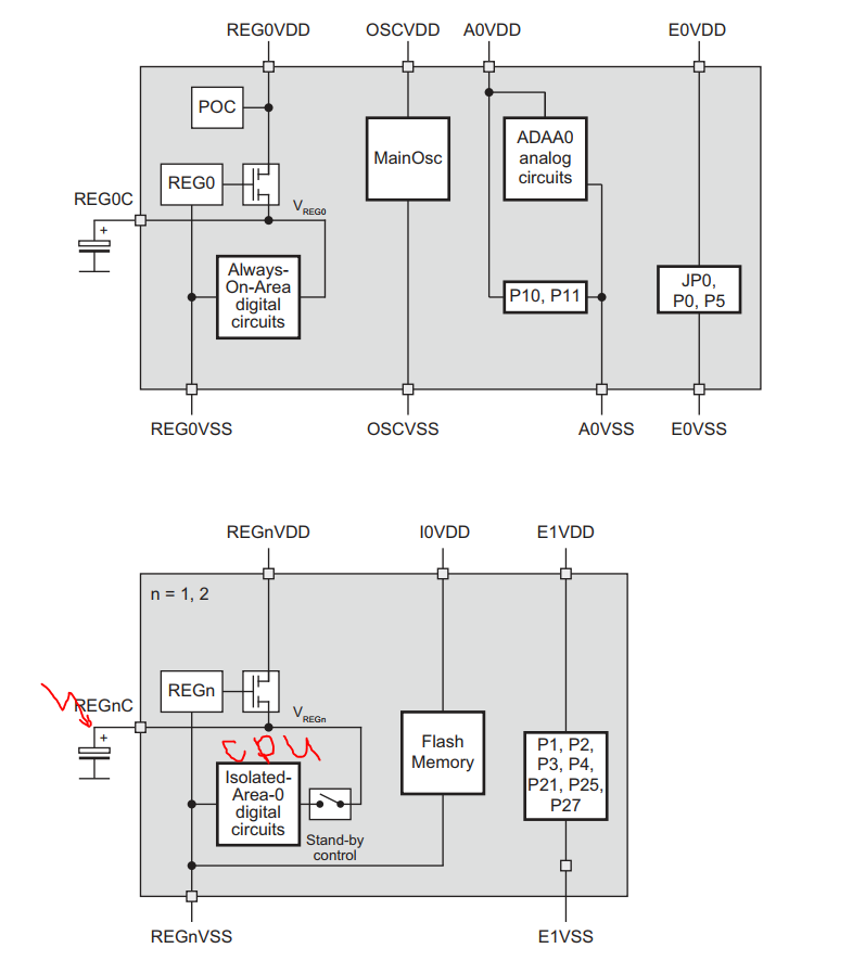
The target uses a Renesas V850E2 microcontroller with a fairly complicated power domain scheme, as compared to the targets I’ve been playing with recently. In particular, there are two internal voltage regulators, REG1 and REG2, which provide power to the CPU. I am assuming I should aim at disturbing the voltage they produce. Here is a schematic:
My plan is to glitch the MCU at pin REG1C first and see what happens. Then, if no success, I’ll do the same with REG2C pin. The voltage on those two pins is 1.5 V, and I think they’re connected internally - at least I could not trace them being connected via tracks on the PCB, and the multimeter indicates they’re shorted.
There’s an interesting talk and slides at chip.fail, which describes using an external voltage supply for a sort-of identical setup. Basically, they desolder the capacitor connected to the internal regulator, and supply external voltage to the pin. I don’t believe that is going to be useful in my case, so I’d like to hear your comments.
Edit: I am also having trouble identifying the low-voltage regulator and inserting a resistor between its output and the MCU power pins. In one of Colin O’Flynn’s videos, I noticed he’s not using a resistor when glitching a RPi 3. Can this be done?
That sounds good for the most part. I’m not sure if you’ll have to feed in your own voltage supply to get a glitch here. I know we do that on similarly powered CW target boards, but I feel like that’s more for power analysis than glitching, though if you run into issues, that may be a good place to start.
Regarding not using a shunt resistor, it definitely can be done. The resistance between the power supply is effectively just another parameter in the glitch. If you don’t use one, you’ll get a lot of ringing on the power line, which can be good or bad for glitching.
I have the feeling that the multiple capacitors, attached to the REGnVDD rail will thwart the glitch. In addition, the capacitor on the internal voltage regulator output will also do the same.It’s probably worth working through both cases.
In addition, the same supply is used for the rest of the MCU’s power pins, some of which have a brown-out detector functionality.
Why do you think the core is supplied by two separate regulators in the chip?
If you feed a slightly higher voltage into the internal voltage regulator output, it should disable the internal regulator entirely, so if you do that, I don’t think you’ll have to worry about the capacitance on the input to the voltage regulator. Otherwise, I think they’ll interfere your glitch. I’d recommend removing the capacitors on the REGnC pin.
I’m not sure why two voltage regulators are used. Perhaps you can find something in the chip reference manual/datasheet, if it’s available.
I haven’t thought of using higher voltage on the REGnC pin, as the datasheet specifies it at 1.5V +/- 150 mV. So what I was planning is not supplying the REGnVDD pin at all, and manually supplying the internal circuitry through the REGnC pin with 1.5V. Using this method I think I will avoid the capacitance on the REGnVDD rail.
The datasheet does not say anything about the two regulators supplying the core. My guess is that it is logically separated into different domains, and I will try disabling each regulator and see if the MCU still runs. The case may be that for glitching I don’t need to supply both regulators.