I own both the CW Lite and the CW 1200. I also got the UFO Target board and recently bought the Aurix Target Board. How do I set it up from scratch to perform a simple testing AES CPA attack on it? Can I still use my old code from the notebooks? I see that I need to download a Tricore toolchain to build projects (I assume the same projects as in the CPA tutorials?). Do I need to modify the code somehow to set up a trigger signal? I am kind of lost here
Follow the instructions for building and programming here:
I would expect that our AES tutorials should “just work” if you’re using the same tinyaes implementation (i.e. building with make PLATFORM=CW308_AURIX CRYPTO_TARGET=TINYAES128C).
Glitch tutorials will be interesting if you enable the lockstep core.
I have bought the infineon miniwiggler v3 but it doesnt contain a 20pin adapter, the wiggler has smaller pins than the ones from the CW Target Board. How can I fix that problem?
@jpthibault I did try to connect the wires by myself, although I cannot find the nRST from CW308 PIN on the Infineon Miniwiggler PINs, which one could it be?
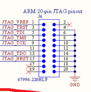
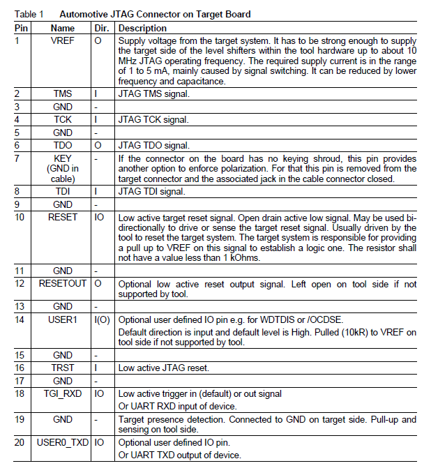
I think it would be pin 10.
I created an adapter for the JTAG between miniwiggler and cw308, although I get following message when I try to connect the target via memtool:
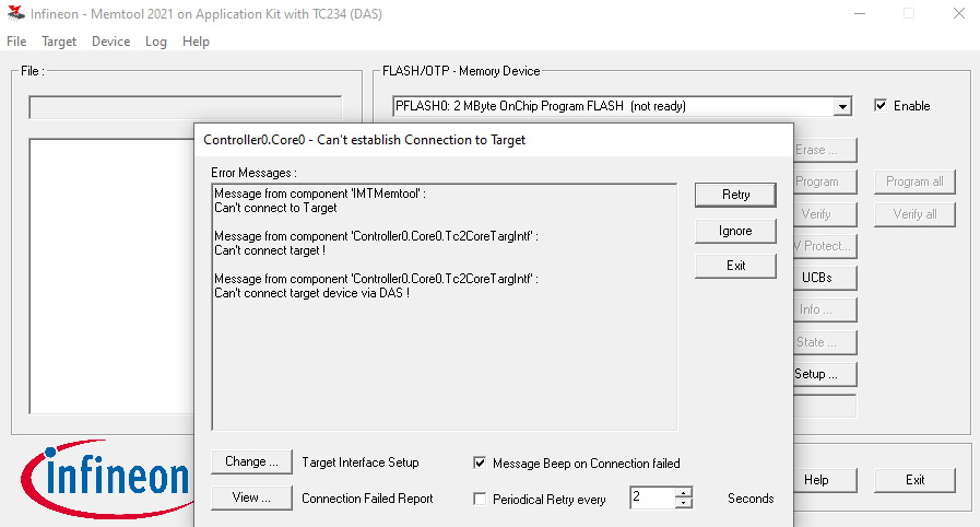
What could cause the problem? Are there other effective ways to program the aurix chip to make it compatible with the jupyter notebooks?
The report:
----------------------------------------------------------

  Connection Failed Report from
  Infineon Memtool Target Interface, Version: 1.19.9
  created: 05/05/22, 11:48:54

----------------------------------------------------------

Windows version:
  Win8 ()
  Admin: yes

IMT version:
  Release:  2021.05
  Build:    5005
  Path:     C:\Program Files\Infineon\Memtool 2021

Target configuration file:
  C:\Users\Documents\Infineon\IMT 2021\Targets\AppKit_TC234_das.cfg

Error messages:
  Controller0.Core0.Tc2CoreTargIntf: Can't connect target !
  Controller0.Core0.Tc2CoreTargIntf: Can't connect target device via DAS !

Settings:
  PortType:  DAS
  CommDevSel:
  TargetPort:  Default
  TargetPortId:  553582592
  DasIsDefault:  n
  MaxJtagClk:  10000
  CheckJtagId:  y
  ScanJTAG:  n
  Ocds1ViaPod:  n
  EtksArbiterMode:  None
  EtksWaitAfterArbitrationTime:  0
  RefreshJtag:  n
  RefreshHarr:  n
  ReenableOcds:  y
  ReduceJtagClock:  n
  UseDap:  n
  DapMode:  2PIN
  JtagMuxPort:  -1
  UseNewJtagEngine:  y
  ConnOption:  Default
  SetDebugEnableAb1DisablePin:  n
  ResetWaitTime:  500
  ResetMode:  Default
  OpenDrainReset:  n
  DiswdtOnReset:  n
  ExecInitCmds:  y
  InitScript Script:
    ; Workaround for TLF35584 B/C-Step Bug

    # QSPI2_CLC: Enable QSPI module. DISR=0,EDIS=1
    SET 0xF0001E00 0x8

    # QSPI2_GLOBALCON: Set the Global time quantum and Expect phase timeout in GLOBALCON register.
    # Also, enable Master mode.  MS=0, STROBE=15, EXPECT=12, TQ=0
    SET 0xF0001E10 0xF3000

    # QSPI2_PISEL: Select the Master Mode Receive Input in the PISEL register. Here, it is
    # input A (MRST0A). MRIS=0
    SET 0xF0001E04 0x0

    # QSPI2_GLOBALCON1: Enable the Single Move Mode in the GLOBALCON1 register.
    # TXFM=1, RXFM=1
    SET 0xF0001E14 0x14050000

    # QSPI2_ECON1: Enable Parity, and set values for Q, B and C fields in the ECON4 register
    #(since chip-select output 1, SLSO21 is used here). PAREN=1, C=0, B=2, A=1, Q=9
    SET 0xF0001E24 0x4249

    # QSPI2_SSOC: Enable the slave select output (Here SLSO21) and make the corresponding
    # signal active level low, in the SSOC register. OEN=0x80, AOL=0
    SET 0xF0001E48 0x00020000

    # P14_IOCR0: P14.2=SLSO21;
    SET 0xF003B410 0x00980000
    # P15_IOCR0: P15.3=SCLK2;
    SET 0xF003B510 0x98000000
    # P15_IOCR4: P15.5=MTSR2, P15.7=MRST2B
    SET 0xF003B514 0x00009800

    # QSPI2_FLAGSCLEAR
    SET 0xF0001E54 0xFFF

    # QSPI2_BACONENTRY: In the BACON register: Set the current frame as the last frame, and data
    # length in bits (Short frame mode). Data length is 15 bits + parity, MSB is shifted
    # first. The channel is selected properly (Here, channel 1 for SLSO21) Set
    # the trailing delay. CS=QSPI_SLSO,DL=14,BYTE=0,MSB=1,UINT=0,PARTYP=0,TRAIL=0,
    # TPRE=3,LEAD=0,LPRE=3,IDLE=0,IPRE=3,LAST=1
    SET 0xF0001E60 0x17206187

    # QSPI2_GLOBALCON: Put the QSPI module to RUN state.  MS=0, STROBE=15, EXPECT=12, TQ=0, EN=1
    SET 0xF0001E10 0x010F3000

    # QSPI2_DATAENTRY0: Write w parity   0x43AB,0x43EF,0x4356,0x4312,0x4693,0x4500,0x43DF,0x4334,0x43BE,0x43CA
    # UNLOCK1
    SET 0xF0001E64 0x43AB

    # QSPI2_FLAGSCLEAR: Clear TX flag. TXC=1
    SET 0xF0001E54 0x200

    # QSPI2_FLAGSCLEAR: Clear RX flag. RXC=1
    SET 0xF0001E54 0x400
    # QSPI2_DATAENTRY0: UNLOCK2
    SET 0xF0001E64 0x43EF

    # QSPI2_FLAGSCLEAR: Clear TX flag. TXC=1
    SET 0xF0001E54 0x200

    # QSPI2_FLAGSCLEAR: Clear RX flag. RXC=1
    SET 0xF0001E54 0x400
    # QSPI2_DATAENTRY0: UNLOCK3
    SET 0xF0001E64 0x4356

    # QSPI2_FLAGSCLEAR: Clear TX flag. TXC=1
    SET 0xF0001E54 0x200

    # QSPI2_FLAGSCLEAR: Clear RX flag. RXC=1
    SET 0xF0001E54 0x400
    # QSPI2_DATAENTRY0: UNLOCK4
    SET 0xF0001E64 0x4312

    # QSPI2_FLAGSCLEAR: Clear TX flag. TXC=1
    SET 0xF0001E54 0x200

    # QSPI2_FLAGSCLEAR: Clear RX flag. RXC=1
    SET 0xF0001E54 0x400
    # QSPI2_DATAENTRY0: WWD off
    SET 0xF0001E64 0x4693

    # QSPI2_FLAGSCLEAR: Clear TX flag. TXC=1
    SET 0xF0001E54 0x200

    # QSPI2_FLAGSCLEAR: Clear RX flag. RXC=1
    SET 0xF0001E54 0x400
    # QSPI2_DATAENTRY0: ERR-pin monitoring off
    SET 0xF0001E64 0x4500

    # QSPI2_FLAGSCLEAR: Clear TX flag. TXC=1
    SET 0xF0001E54 0x200

    # QSPI2_FLAGSCLEAR: Clear RX flag. RXC=1
    SET 0xF0001E54 0x400
    # QSPI2_DATAENTRY0: LOCK1
    SET 0xF0001E64 0x43DF

    # QSPI2_FLAGSCLEAR: Clear TX flag. TXC=1
    SET 0xF0001E54 0x200

    # QSPI2_FLAGSCLEAR: Clear RX flag. RXC=1
    SET 0xF0001E54 0x400
    # QSPI2_DATAENTRY0: LOCK2
    SET 0xF0001E64 0x4334

    # QSPI2_FLAGSCLEAR: Clear TX flag. TXC=1
    SET 0xF0001E54 0x200

    # QSPI2_FLAGSCLEAR: Clear RX flag. RXC=1
    SET 0xF0001E54 0x400
    # QSPI2_DATAENTRY0: LOCK3
    SET 0xF0001E64 0x43BE

    # QSPI2_FLAGSCLEAR: Clear TX flag. TXC=1
    SET 0xF0001E54 0x200

    # QSPI2_FLAGSCLEAR: Clear RX flag. RXC=1
    SET 0xF0001E54 0x400
    # QSPI2_DATAENTRY0: LOCK4
    SET 0xF0001E64 0x43CA

    # QSPI2_FLAGSCLEAR: Clear TX flag. TXC=1
    SET 0xF0001E54 0x200

    # QSPI2_FLAGSCLEAR: Clear RX flag. RXC=1
    SET 0xF0001E54 0x400

    ; switch off FLASH error traps
    SET 0xF80020A8 0x8000
    SET 0xF80020AC 0x8000

  ExecOnConnectCmds:  n
  OnConnectScript Script:
    Script is empty
  ExecOnExtRstCmds:  n
  ResetPulseLen:  10
  AddResetDelay:  0
  UseTrstOnReset:  n
  ExecEmemInitOnReset:  0x00000000
  SimHsmBootEnabled:  n
  UnlockInterface:  n
  BootPasswd0:  0x00000000
  BootPasswd1:  0x00000000
  BootPasswd2:  0x00000000
  BootPasswd3:  0x00000000
  BootPasswd4:  0x00000000
  BootPasswd5:  0x00000000
  BootPasswd6:  0x00000000
  BootPasswd7:  0x00000000
  PasswordFile:
  UnlockInterfaceDelay:  -1
  HandleBmiHeader:  n
  SetAutOkOnConnect:  n
  DontUseWdtSusp:  n
  InitCore0RamOnConnect:  n
  IgnoreFailedHaltAfterResetOnConnect:  n
  TrySystemResetAfterFailedHardwareReset:  n
  RunStabilityTestOnConnect:  n
  RunStabilityTestCycles:  10
  IgnoreFailedEnableOcdsOnConnect:  n
  UseLbistAwareConnect:  n
  MaxTry:  1
  ForceEdMode:  -1
  UseDflashAccessFilter:  y
  DetectResetWhileHalted:  y
  UseTranslateAddr:  y
  DownloadToAllRams:  y
  HaltAfterReset:  y
  HaltAfterHardwareReset:  n
  TargetAppHandshakeMode:  None
  TargetAppHandshakeTimeout:  100
  TargetAppHandshakeParameter0:  0x00000000
  TargetAppHandshakeParameter1:  0x00000000
  TargetAppHandshakeParameter2:  0x00000000
  TargetAppHandshakeParameter3:  0x00000000
  ConvertSuspendSignalToPulse:  n
  SimioAddr:  g_JtagSimioAccess
  UseStmForPtm:  1
  ExecOnStartCmds:  n
  OnStartScript Script:

  ExecOnHaltCmds:  n
  OnHaltScript Script:

  ExecOnHaltCmdsWhileHaltedPeriod:  0
  UseTriggerToBreak:  y
  UseTL2OnHalt:  y
  UseOstateStable:  y
  AllowJtagResetWhileRunning:  y
  MaxAccRetry:  1
  AccRetryDelay:  10
  DefOcdsReserved:
  UseRestartWhileRunningHandling:  n
  DebugResetOnDisconnect:  n
  IgnoreEmemAccessErrors:  n
  RemapEmemAccess:  n
  EnableAutomaticHsmStart:  n
  EnableAutomaticHsmRunControl:  n
  ReadPmcsrWhileRunning:  y
  MultiChipDbgMode:  0
  MultiChipDbgInp:  1
  MultiChipDbgOut:  6
  MultiChipDbgCtl:  7
  IgnoreShortHalt:  n
  HaltOnBreakOnly:  n
  IvIcacheOnHalt:  y
  IvPlbOnHalt:  y
  SuspendSlaveCores:  n
  FilterMemAcc:  y
  DasDllPath:  das_api.dll
  DasHost:
  DasTryStartSrv:  y
  DasSrvPath:  servers\udas\udas.exe
  DasStopSrv:  y
  DasResetHelperBreakAddr:  main
  DasResetMode:  2
  DasRemoveLogFile:  n
  DasForwardSerNum:  n
  DasSrvSel:  -1
  DasPortType:  0
  DasPortSel:  0
  DasCmdTimeout:  1000
  DasWaitAfterConnect:  0
  DasDisconnectSrv:  n
  DasResetDelay:  0
  DasWaitAfterGo:  0
  DasApiLogging:  n
  GoExtOption:
  DontUseTriggerLines:  n
  DontUseSingleStep:  n

JTAG target infos:
  JTAG-ID:           0x00000000
  UsedJtagClk:       0 MHz
  ExtVoltage:        0.0 V
  IntVoltageUsed:    n
  CHIPID:            0x00000000
  STSTAT:            0x00000000

DAS related information:
  DAS DLL Version:
  Server started by UDE:  C:\Program Files\DAS64\servers\udas\udas.exe
  Server name:            UDAS
  Server manufacturer:    Infineon
  Server version:         V3.11
  DAS-API version:        V4.2
  Server lib version:     V3.0
  last DAS error:         4
  last DAS function:      connect_to_device
Hi,
Using one of these: https://www.digikey.ca/en/products/detail/olimex-ltd/ARM-JTAG-20-10/3471401, I’m able to connect. Which connector on the programmer are you using? The correct one is the 10-pin connector closest to the QFP.
Alex
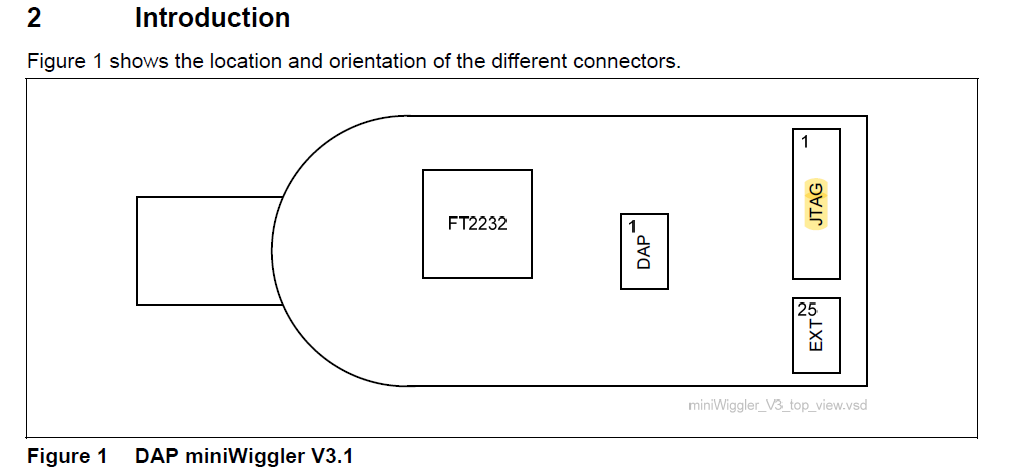
I have connected the 20pin JTAG from the miniwiggler into 20pin JTAG on the CW308(actually only 9 pins). The one you mean is the DAP connector on the miniwiggler which contains 10pins? If yes, how do I know which pins from the miniwiggler DAP belong to which pins on the 20 JTAG of CW308, so I can create a new adapter? I cant find it in the infineon documentation
Yup, the DAP connector is correct. The schematic for the connector that I’m using is available here: https://www.olimex.com/Products/ARM/JTAG/ARM-JTAG-20-10/resources/ARM-JTAG-20-10-schematic.pdf
Alex
alright, Ill try it out, although why doesnt it work through the 20pin JTAG? Do I need to activate it somehow?
I’m not sure why it doesn’t work through JTAG, sorry.
Do I need to use HighTec’s Tricore Tool Chain to create projects for CW? I just created the .hex file using the jupyter notebook (just as in every other case before) and flashed it via the wiggler. Am I missing something here?
So long as tricore-gcc and the other tools are on your PATH, that should be right.