Smart card (EAL5+) power traces

For those who might find this interesting to see…

There is too little public information about side channel attacks against smart card’s HW AES. So, I decided to share some findings here.

The target smart card is pretty old NXP Jcop 2.4.1 card released in late 2000’s

The main benefit is ability to install own applet on the card and use Java crypto API. On runtime, the NXP’s JCVM invokes low level HW AES accelerator. It looks like a good target.

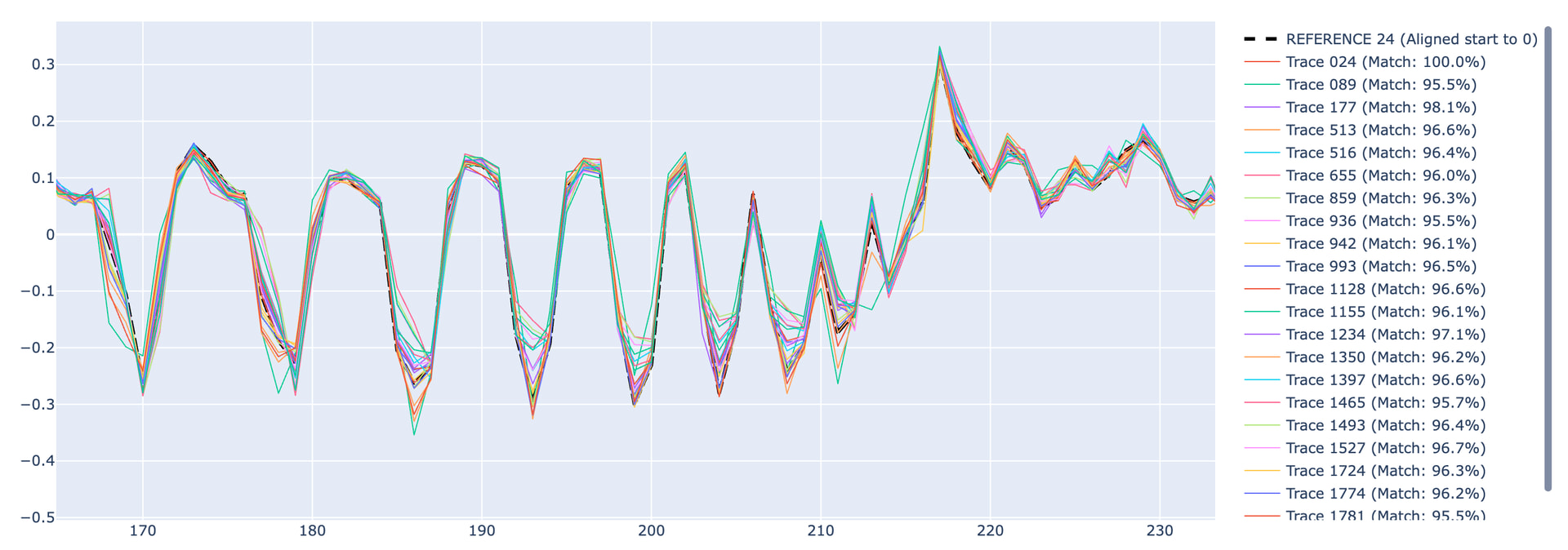
To sync encryption and power traces capturing, I use the edge count trigger to the well known APDU message which sends the plaintext to the card. On triggering the edge counter, the embedded logic analyzer starts counting the samples on the IO SC line to detect first start bit of the smart card reply. This helps me to locate the crypto interval (request - response) very precisely.

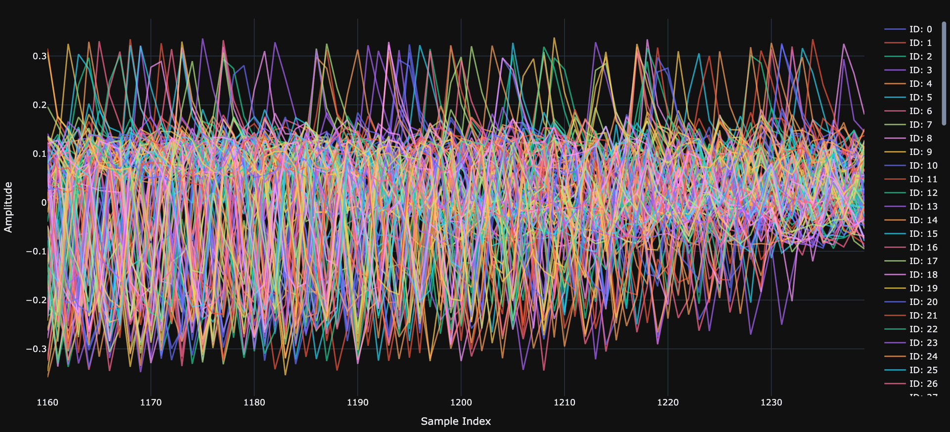
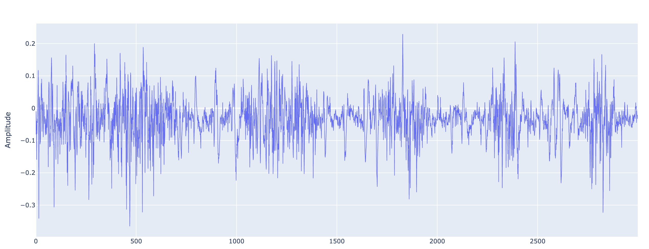
The next step is to locate the HW AES itself as the crypto interval is ~90K samples. I use such trick

        for (short i = 0; i < (short) 10; i++) {
            eepromMarker[i] = (byte) 0xAA;
        }


        aesCipher.doFinal(buffer, ISO7816.OFFSET_CDATA, (short) 16, buffer, (short) 0);


        for (short i = 0; i < (short) 10; i++) {
            eepromMarker[i] = (byte) 0x55;
        }

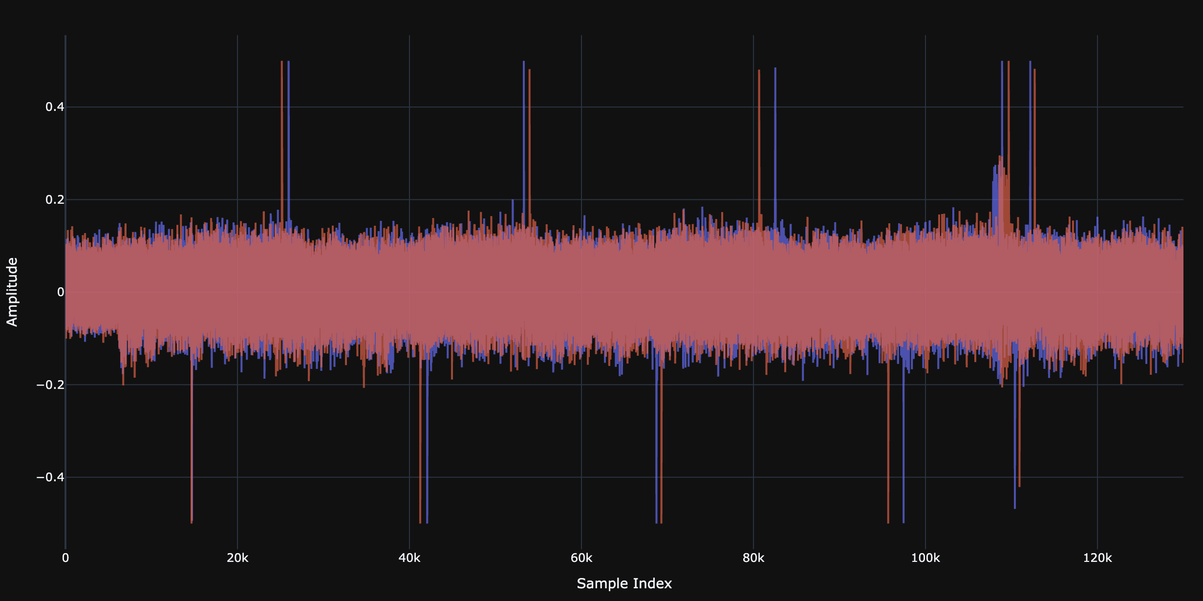
to trigger heavy power consumption EEPROM write activity. This helped a lot me to identify the AES range quickly. As expected, AES was surrounded by sharp and deep spikes.

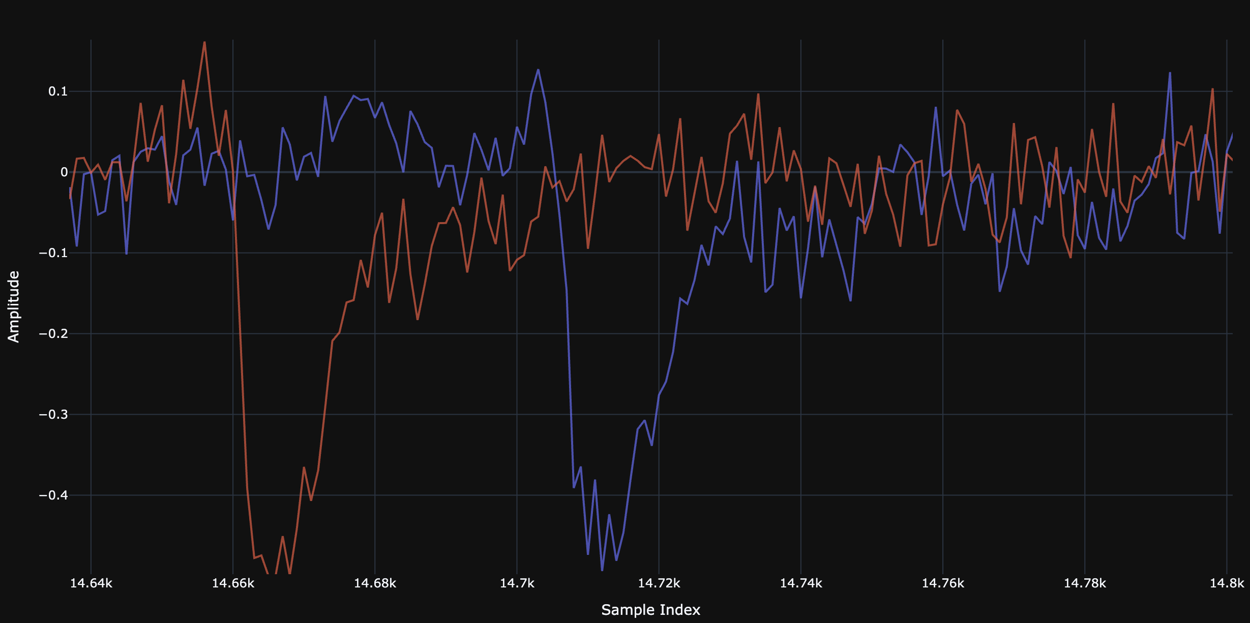
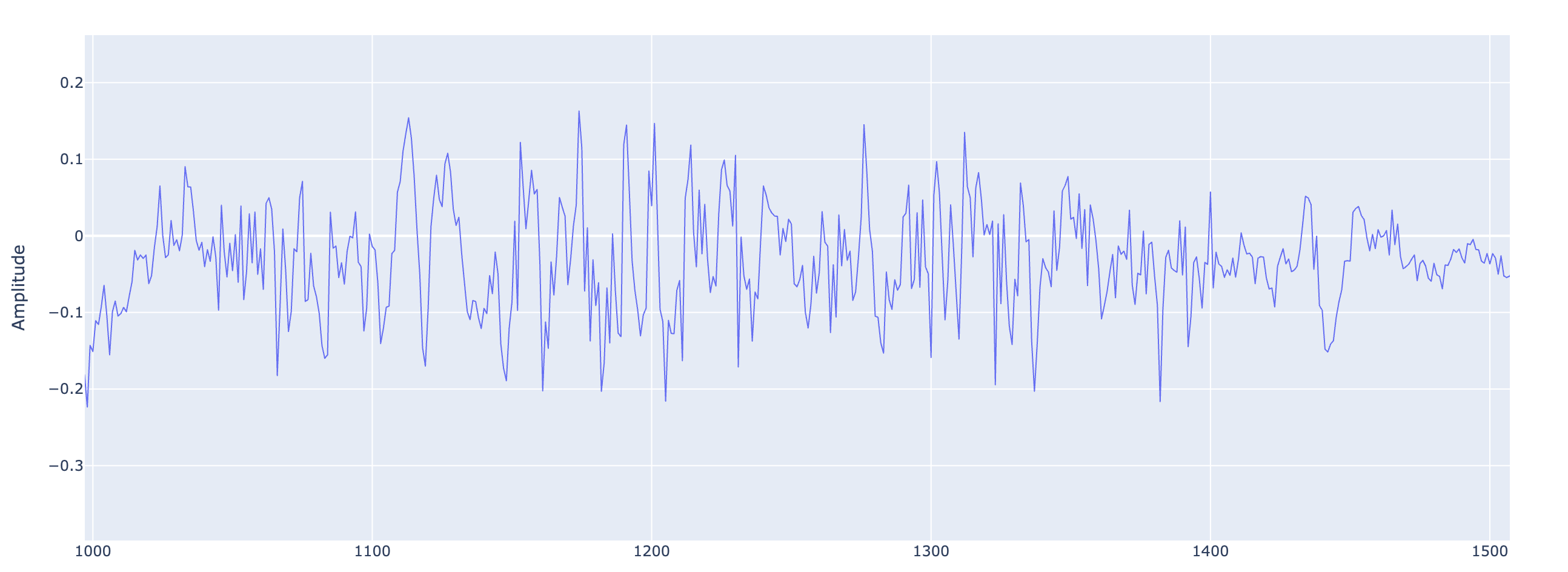
Here is the picture of aesCipher.doFinal(buffer, ISO7816.OFFSET_CDATA, (short) 16, buffer, (short) 0);

I am not sure what exactly happens here, in this zoom in picture. In my opinion it is very noisy trace.

Look at this noise hell

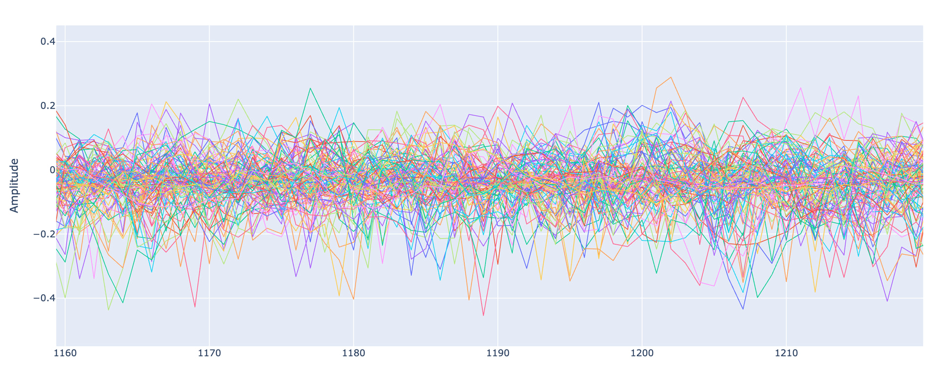
In my opinion, there are no chances to break through this noise.

1 Like

At the same time, I was able to break the smart cards where the clock jitter and noise insertion countermeasures are not so heavy.

I found that using of normalized cross correlation works better than just SAD.

Above picture is a result of applying the NCC algorithm to the set of totally misaligned traces. Some traces were shifted up to 25-30 samples relative to the reference trace. But most of noisy traces were just dropped as they have similarity in best case up to 70% due to smart card countermeasures.

It slides the specified window size of the reference trace over all samples of each trace to find the required similarity (95% in this specific case). Then it creates the new aligned set by hard shifting of matched range to the reference trace.

So, this aligned set looks more promising for running the SCA.

Here is the picture of how it looks like right after trace capturing (these are the same traces before applying NCC):

2 Likes

@jpthibault Hello

Whether I correctly understand I cannot trigger the ‘nrst‘ output of the CW Husly using scope.trigger.module = 'edge_counter'

And there only an option is to mount the SMA on the reset line of the smart card and control it by crowbar output of Husky, in other words, by VCC glitch.

There are interesting attack scenarios by running the warm reset of the SC.

Why not? Just set scope.trigger.triggers to nrst: Scope API — ChipWhisperer Documentation

Thanks for sharing this, the cross correlation to align traces looks like a very interesting thing to try with my own research.

Thanks. Glad to hear it is possible. Will check it later…

Let me clarify my original problem…

The proposed solution sets up the trigger module to listen the ‘nrst‘ line as an input and generate a trigger when the ‘edge_counter‘ counts specified number of pulses.

My question was whether it is possible to manage the ‘nrst‘ line when trigger is happened.

For example, the edge_counter trigger listens the IO_SC line, when specified number events on this line is happened, the logic level on the ‘nrst‘ line should be changed to initiate the warm reset of the smart card.

So, I supposed that VCC glitch can be used for this purpose.

The idea is some event triggers the edge_counter trigger → the crowbar output connected to the SC Reset line pulls down the line for the specified period → pulls up the SC Reset line back.

@NewDwarf I use RP2350 and its mini-fpga for similar purposes. Very simple operation of T=0 T=1 smartcards protocols or operation in UART mode. The only thing I still miss in this glitcher is a precise clock glitch generator that can be added using ready-made systems (apart from FPGA). In chipwhisperer husky or lite you will have to spend a lot of time to implement these functions in ARTIX A7 or VIRTEX, in my opinion it is style over substance. - cw-lite and husky crowbar do not work on any smartcards released after 2010, they were tested on similar devices. Maybe your cards are some low-cost design and that’s why the vcc glitch is working for you…

Perhaps your glitches only disturb I/O transmission - but do not affect the processor core executing the code. For example, I can change 1 or several ATR bytes on any new smartcard, even EAL6+, but in fact these glitches do not affect the program counter and are useless.

It is very simple to verify whether the glitches work - the smartcard will be blocked very quickly if your glitch actually modifies something, if the glitches do not work the smartcard may provide variable ATR bytes but you can glitch it for months and it will still work. I hope you understand what I’m writing about.

In short smartcards with an anti-glitch sensor require a very narrow window for VCC and EMP glitches. - You cannot make such a window using the current HW CW-husky.

Ah, now I understand.

The proper way to do this would be to use the new scope.bitbanger function.

You would set up a sequenced trigger, where the first trigger module in the sequence is your edge counter, and the second trigger module in the sequence is the bitbanger.

The bitbanger gives you the ability to send the configured glitch (as per scope.glitch, as usual) directly onto the nrst line. This notebook covers the usage basics. However glitching the nrst line can only be done with the Husky Plus - I couldn’t make that fit on the Husky; the bitbanging glitch is limited to the USERIO pins (so possibly you can re-wire your target board to use a USERIO pin as nrst).

(I am working on some optimizations that may make it possible to do away with this Husky limitation – no promises.)

@NewDwarf EMP glitches on secure smartcards have a similar effect to voltage glitches in my experience – some ATR bytes change, but this is only interference with I/O transmission. It’s possible that the glitch is leaking into the I/O and causing errors. The first ATR byte, or the first two bytes, or a few bytes in the middle of the ATR are changing – this isn’t a glitch. When I scan the pico-EMP area on the cnc3018 and encounter “sensitive” areas, the effect is exactly the same – maybe a little more severe than with crowbar, but it’s still not a working glitch that has changed anything in the processor. If it were a glitch, the ATR statuses would be different, like 3B 00 00 00 instead of 3B 28 B4 A1, which they aren’t. The sensors on these smartcards are capable of detecting glitches with widths exceeding 2ns, so the glitches don’t work. Today, you can build a 10ns-2ns voltage glitcher, but EMFI (EMP) that generates glitches of such narrow widths is impossible today and won’t be for many years to come. Smartcards released after 2010 were tested on the Riscure EMFI, and the attached document indicates that some of them reacted to glitches. This is interesting… I need to buy a Java smartcard and test it on EMFI. So far, I’ve tested other smartcards. What atr statuses do you get on your glitch SLE66 java card? Check this pdf https://pure.tue.nl/ws/files/46956556/770549-1.pdf :wink:

@chipquik I think it is useless to just glitch the smart card blindly. The glitch is the helper to run the pushed shellcode which break MPU/firewall restrictions.

Glitching of the SLE66 is absolutely possible. Proved by dumping the SLE66 card.

Right smartcards get blocked very quickly if your glitch actually works, and only then. In the case of SOC processors, etc., they can be glitched hundreds of thousands of times and still work. Furthermore, smartcards have very difficult attacks, executing instructions at different times, and many other security features – this is the fundamental difference between an SOC and a smartcard – with the latter, you’d need to have a ROM dump or sacrifice damaging hundreds of identical smartcards before you succeed.

@NewDwarf Did you use segmented capture in chipwhisperer-husky to implement the cross-correlation method? This method of recording a long record reduces the sample rate by a factor of 10. Another method is to use an SAD trigger to capture individual AES operations. I ask because in my case, the shuffling is very extensive. I don’t know of any other method than recording the entire trace, which contains the full AES fragmented into single sequences. 200 m/s : 10 = 20 m/s of desynchronized trace, unless in your case you have a synchronized clock dut with the chipwhisperer? Even if this synchronization works, in some cases a random number generator may be used.

No. Regular capture.

SAD doesn’t work here.

Same in my case.

Use regular capture and capture as close as possible to the crypto operation you are looking for.

I know you are familiar with the Viaccess CAS and possibly talk in context of this CAS.

For example, one of the good candidate to study is checking of the signature of the arbitrary ECM message. Just prepare any valid ECM which would include two control words (EA 10) and a signature (F0 08). The expected status word is 90 40 (Wrong signature). So you goal is to trigger capturing of the traces right after sending the last bit of the last byte of the ECM and stop capturing on getting the start bit of the status word. You can measure these intervals by a logic analyzer or use LA functionality of the CW Husky.

I did a quick captures for the smart card 3F77180000C11401A2689000 (this is Via 2.5 or 2.6 based on SLE66).

Below is the complete capture of ECM processing which returns SW 90 40. I have no idea about the algorithms but this trace tells many things for us:

  1. Activity in the range of 8-10K. This is memcpy of the key from EEPROM to RAM
  2. The key store in the EEPROM is 16 bytes lenght and stored in encrypted form. So, next two spikes are random number generator activity to charge random numbers to hide the DES S-boxes. Next two spikes at 17K and 23K is DES decryption of the encrypted key which will be used for checking the ECM signature
  3. We passed two control words (each 8 bytes). Next 6 spikes are random number generator activity for two consecutive 3DES operation.
  4. At 110K secure memcmp (based on randomization) of the calculated and obtained signature.

If you are familiar with signature algorithm, please, confirm. But this is definitely not AES!

Regarding syncronization. The card gives us perfect clues - sharp spikes which are beginning of the crypto algorithms. Zoom in the traces, learn their similarities first and then apply cross correlation algorithm. You can clearly see how one trace drifts relative to another.

so this is still something that I definitely still don’t understand today.

It should work if you use multiple patterns with multi-triggers

Yes, that’s right, but your system is very old. It does not have as much protection in the “software” layer against side-channel attacks/analysys as mine. Whatever you have there is a hardware countermasure. In my case, I tried to recreate the power model and generate templates when analyzing the known aes-128 session key - this key is known and that was the initial goal.

via_complete - looks like a typical power trace from infineon - no, it is not aes. sle66/88 models

Regarding syncronization. The card gives us perfect clues - sharp spikes which are beginning of the crypto algorithms. Zoom in the traces, learn their similarities first and then apply cross correlation algorithm. You can clearly see how one trace drifts relative to another.

I will come back to playing with smartcards when I have more time.

I haven’t used Husky so far… I have a powerful external logic analyzer.

Why not HMAC-SHA256 for signature ? If you truncate to 16 bytes ….

HMAC-SHA256 has another pattern. The signature this card use is 8 bytes.

Hello NewDwarf,

I hope you are doing well and that your project is going smoothly.

I am fairly new to side-channel analysis, and I am currently working on something similar. I came across your work and thought it would be worth reaching out, although I know everyone is busy and random messages from strangers are usually not the highlight of anyone’s day.

I have a Java Card that I bought randomly from the market. At first, I did not even know its exact model, but after checking the ATR, I found that it appears to be a Feitian A40, with the following ATR:

3B 9F 95 81 31 FE 9F 00 66 46 53 05 10 00 FF 71 DF 00 00 00 00 00 EC

The ATR information seems to match data provided by Radboud University.

I have successfully uploaded an AES applet to the card. For my setup, I am using a LEIA Solo card reader, mainly for triggering, and a ChipWhisperer Husky for trace capture.

It took me quite some time just to understand the Husky and the LEIA reader properly. After that, I captured some quick traces and tried CPA, but, unsurprisingly, I did not get anything useful at first. So I went back to reading and trying to understand the process better.

I wanted to ask, from your experience, whether it is realistically possible to make some progress with this kind of setup and card, or whether there are any obvious limitations I should be aware of before going too far in the wrong direction.

Any guidance, advice, or even small pointers would be highly appreciated.

Thank you for your time.