So I’ve got things setup and “working”. I was able to achieve repeatable results from the first example. The set up is as follows (I won’t provide code here as my working system isn’t network enabled, I will provide snippets as needed, but I have to retype them…):
Plugged in the 7.37 MHz crystal. I’m providing that to HS1 in by jumping the pins labelled crystal and HS1 on the side closest to the board edge (so as to NOT provide it directly to the target). I have HS2 jumped to provide it as the input clock to the target. Based on what I can see on my scope, it is as expected if I use the following:
scope.clock.extclk_freq = scope.clock.freq_ctr
scope.clock.clkgen_src = ‘extclk’
scope.clock.clkgen_freq=scope.clock.extclk_freq*1.5 <<< this was 2
scope.clock.adc_src=‘extclk_x4’
scope.clock.reset_dcms()
scope.clock.resetDcms(). <<< this was based on something suggesting it was needed also
baud = (38400/7.37E6)*scope.clock.clkgen_freq
target.baud = baud
scope.decode_IO.rx_baud = baud <<< Added this based on previous thread…
print(scope.clock.extclk_freq)
print(“Baud = {}”.format(baud))
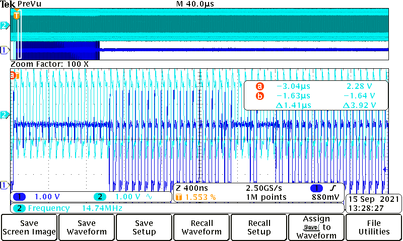
The remaining code is basically what is in the Fault 1_2 setup. The only additional thing I added was something to enable the Aux output so I could trigger the scope around the glitch time. This all “works fine” ™ except that there are periods where the target just resets and if I look at my scope, the AUX output has a whole lot of craziness after the glitch period. When this happens, it seems like things are just going crazy all together. Then it settles for a while and appears to walk the glitch through the glitch period, as expected (via moving the glitch with the glitch controller). But after a good cycle, it goes crazy again. I know 1.5x the clock seems like a weird value, but I was looking for something close to 12MHz… just to see how the target behaved. I didn’t expect what I am seeing on the AUX output (and during this period, when you can see the AUX out just going crazy, there really isn’t a glitch going on). Maybe I’ve accidentally hit some clock limitation?
Scope suggests the clock is 11.08 MHz or thereabout. So that seems to be working.