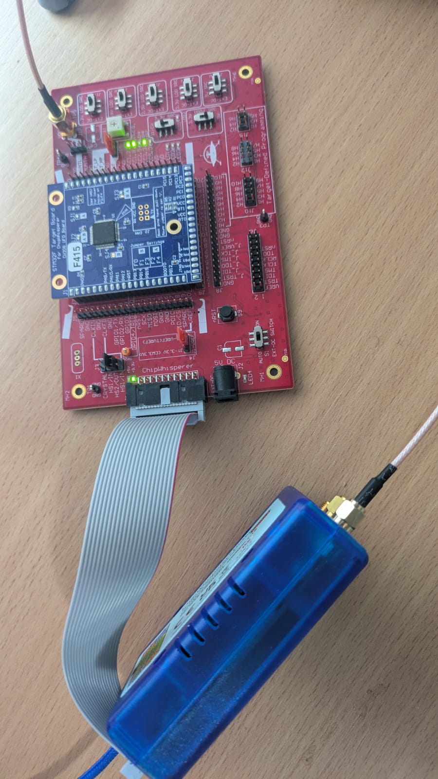
I am running this code on my setup (CW Huskey, UFO Board, STM32F415 target, see picture), and once it managed to capture a proper trace, but every other time it only captures noise, and I either get a ADC clipped error or a trigger to soon error. I am using the simpleserial-base firmware, with the only change being a short loop before the trigger, to add a small delay, and CW 6.0.
import chipwhisperer as cw
scope = cw.scope()
target = cw.target(scope, cw.targets.SimpleSerial) #cw.targets.SimpleSerial can be omitted
scope.default_setup()

import time
msg = bytearray([0]*16) #simpleserial uses bytearrays
#scope.gain.gain = 15
scope.arm()
time.sleep(1)
target.simpleserial_write('p', msg)
scope.capture()
print(scope.errors.adc)
scope.errors.clear()
cw.plot(scope.get_last_trace())
Setup:
This is for a college project, so I have no experience with CW, but my tutor also had no idea what was wrong.
As a first step, you should remove the delay between arming the scope and sending your plaintext. As for clipping, that’s a matter of what you have scope.gain.db set to. Try lowering that.
Can you post a picture of your power trace?
Lowering the db from the default 25 to 24 seems to be enough.
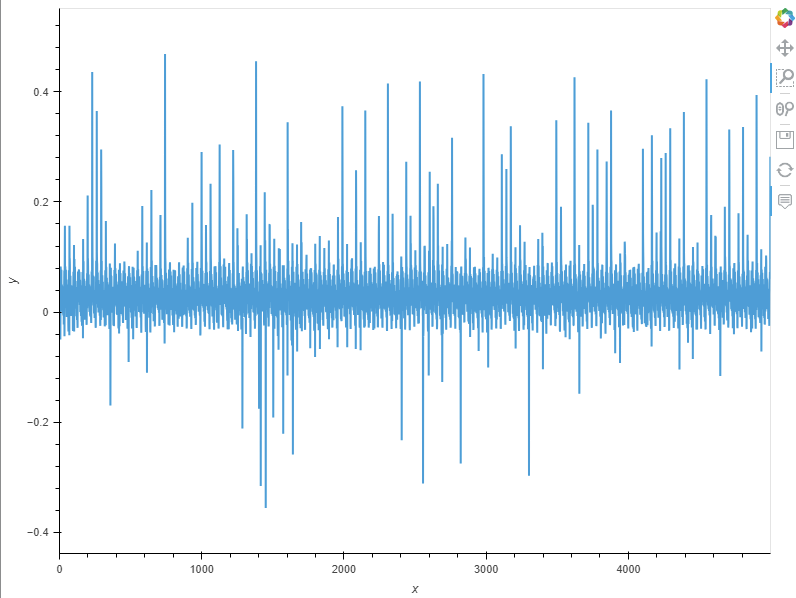
This is what it looks like with your suggestions, sadly I didn’t screenshot the time it worked.
It seems I don’t get a trigger to soon error anymore, but I still get “(ChipWhisperer Scope WARNING|File _OpenADCInterface.py:732) Timeout in OpenADC capture(), no trigger seen! Trigger forced, data is invalid. Status: 13” in my output, and again with status 12.
Can you try toggling the nRST pin after running default setup? There may be some issues with the startup of the clock that can cause the target not to boot correctly.
Added this to my code after default setup:
scope.io.nrst = False
scope.io.nrst = True
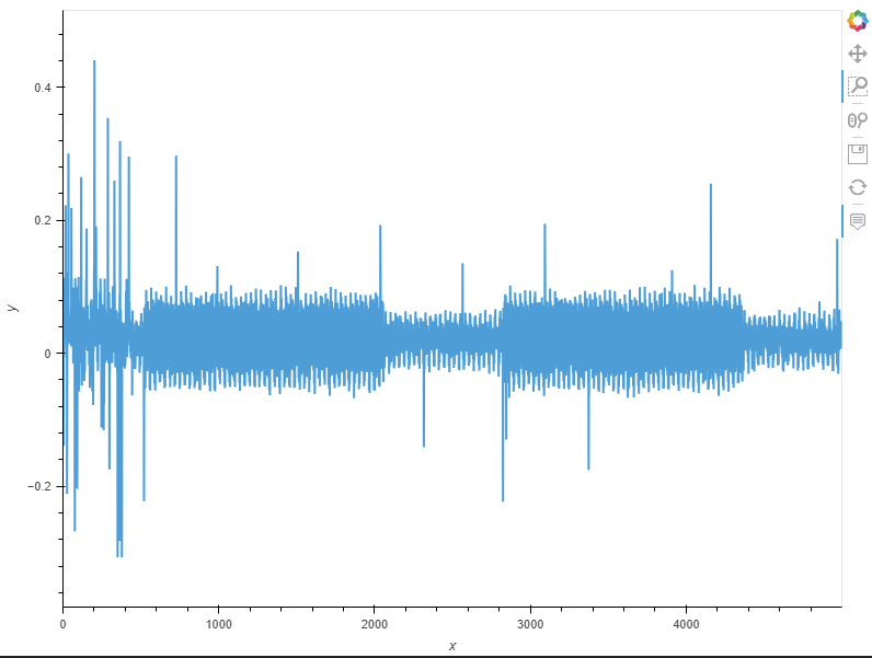
Trace now looks like this, is that what is expected? Errors are gone and it is at least not only noise anymore
That seems more reasonable. You shouldn’t actually see much with the default simpleserial-base firmware, as you’re not doing anything after the trigger. In the future, I recommend adding a time.sleep(0.25) between and after the nRST toggle as well.
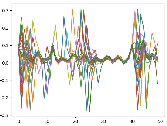
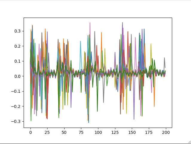
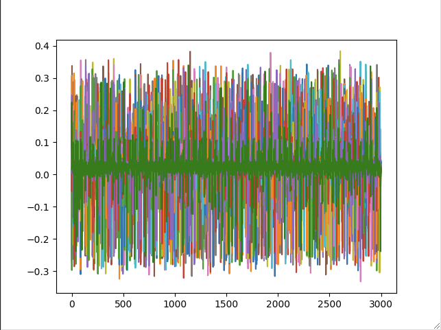
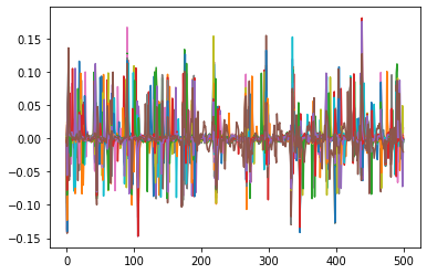
Testing a bit further, it seems that with any more complex task, I still only capture noise, e.g. I now tried to do Lab 2.1B and these are my traces, looking nothing like what is expected (green is the correct trace).
All I did is replace my code with this, taken from the solution for 2.1B
def reset_target(scope):
    scope.io.nrst = 'low'
    time.sleep(0.05)
    scope.io.nrst = 'high_z'
    time.sleep(0.05)

def cap_pass_trace(pass_guess):
    reset_target(scope)
    num_char = target.in_waiting()
    while num_char > 0:
        target.read(num_char, 10)
        time.sleep(0.01)
        num_char = target.in_waiting()

    scope.arm()
    time.sleep(1)
    target.write(pass_guess)
    ret = scope.capture()
    if ret:
        print('Timeout happened during acquisition')

    trace = scope.get_last_trace()
    return trace

%matplotlib notebook
import matplotlib.pyplot as plt
fig1, ax1 = plt.subplots()
fig2, ax2 = plt.subplots()
for c in 'abcdefgijklmnopqrstuvwxyz0123456789h':
    trace = cap_pass_trace(c + "\n")
    if c == 'h':
        ax1.plot(trace[0:200], 'g')
        ax2.plot(trace, 'g')
    else:
        ax1.plot(trace[0:200])
        ax2.plot(trace)
fig1.show()
fig2.show()
Yes, I made sure to flash the correct firmware before testing.
You may need to swap over to the adjustable voltage regulator - the F4 has an internal 1.2V LDO which needs to be bypassed via the decoupling cap pins. We feed in 1.2V, but this might not be enough to overpower the regulator fully. Try measuring out something like 1.25V on the adj reg (adjustable via the white pot on the right side of the board), then swap over to it by changing the jumper on the FILT pin.
It’s still not working, only thing noticeable is that if I enter the correct password, I see the idling behavior after, but sending single characters, they all seem to be just noise. Are my switches/jumpers all set correctly, because otherwise, I am truly out of ideas.
I missed this before, but you shouldn’t have a delay after arming your scope. Can you try using the code from Lab 2_1B verbatim to see if that works?
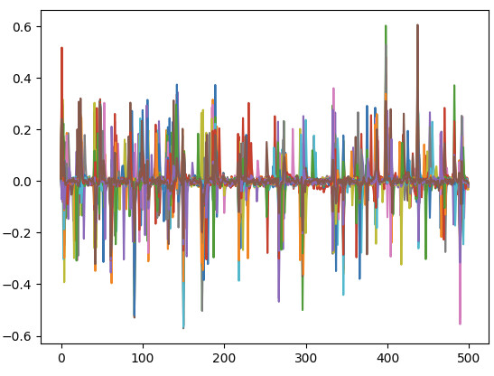
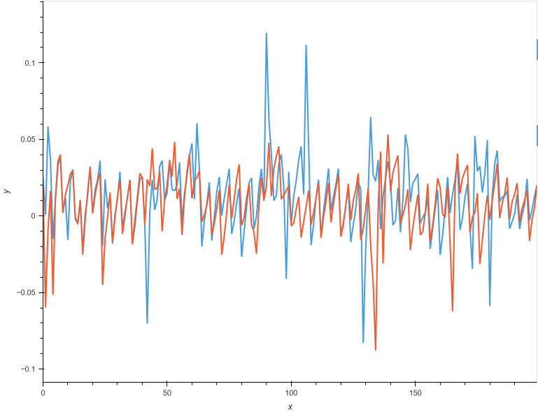
No idea where that debugging tip came from, but running the original code (except resetting the target at the beginning and lowering db) yields the exact same results, here’s a picture of the difference between the traces and a reference trace, where one should clearly be different:
The diff in cell before the full attack is 94 for x (correct) while the others are 60-70, so there is a small difference but the baseline is far noisier than shown in the example. Adjusting the threshold to 75 in the full attack, I get the correct password. Switching back J14 I have the same results.
I also managed to perform the AES DPA/Lab 3.3 (my real goal), but I had to capture 12000 traces instead of the default 2500, so I guess it’s fine for now, and maybe the reference images in the notebooks are just overly ideal versions of what you see, maybe it looks like that with another target.
The DPA lab isn’t a great evaluation, the CPA lab is much better for that. We haven’t done much with the particular combination of the F4 and the Husky, but you shouldn’t be seeing that much noise. Can you try running print(scope) just before you capture and posting the output?
My partner currently has the hardware, but I asked him to do that.
We had a meeting with the tutor today and after some testing and seeing clear results with a CWLITE, they said that apparently edge timings are less consistent on the Husky, leading to noisier traces, but you probably know better if that makes sense or not.
I’m not sure what they mean by edge timings, but everything related to clocking and timing is much tighter on the Husky compared to the Lite. You might be seeing some additional high frequency noise on the lines between the LNA and ADC (there’s a low pass filter between the two on new revisions of the Husky), but this seems especially bad. I’d like to make sure everything is working correctly internally by examining the settings; if the PLL isn’t being locked correctly, for example, that can mess up the capture.
Alex
This is the output:
cwhusky Device
sn             = 50203220325531583330353231323033
fpga_buildtime = 6/10/2022, 10:40
fw_version =
    major = 1
    minor = 5
    debug = 0
gain =
    mode = high
    gain = 22
    db   = 25.091743119266056
adc =
    state                    = True
    basic_mode               = rising_edge
    timeout                  = 2
    offset                   = 0
    presamples               = 0
    samples                  = 5000
    decimate                 = 1
    trig_count               = 938959816
    stream_mode              = False
    test_mode                = False
    bits_per_sample          = 12
    segments                 = 1
    segment_cycles           = 0
    segment_cycle_counter_en = False
    clip_errors_disabled     = False
    lo_gain_errors_disabled  = False
    errors                   = False
clock =
    clkgen_src             = system
    clkgen_freq            = 7370129.87012987
    adc_mul                = 4
    adc_freq               = 29480519.48051948
    freq_ctr               = 0
    clkgen_locked          = True
    adc_phase              = 0
    extclk_monitor_enabled = False
    extclk_error           = False
    extclk_tolerance       = 102.996826171875
trigger =
    module   = basic
    triggers = tio4
io =
    tio1         = serial_rx
    tio2         = serial_tx
    tio3         = high_z
    tio4         = high_z
    pdid         = high_z
    pdic         = high_z
    nrst         = high_z
    glitch_hp    = False
    glitch_lp    = False
    extclk_src   = hs1
    hs2          = clkgen
    target_pwr   = True
    tio_states   = (1, 1, 1, 1)
    cdc_settings = bytearray(b'\x00\x00\x00\x00')
    aux_io_mcx   = high_z
    glitch_trig  = trigger
glitch =
    enabled           = False
    mmcm_locked       = False
    num_glitches      = 1
    clk_src           = target
    width             = 0
    offset            = 0
    trigger_src       = manual
    arm_timing        = after_scope
    ext_offset        = 0
    repeat            = 1
    output            = clock_xor
    phase_shift_steps = 4592
ADS4128 =
    mode      = normal
    low_speed = True
    hi_perf   = 2
LA =
    present                  = True
    enabled                  = False
    clkgen_enabled           = False
    locked                   = False
    clk_source               = pll
    trigger_source           = glitch
    oversampling_factor      = 1
    sampling_clock_frequency = 0.0
    downsample               = 1
    capture_group            = glitch
    capture_depth            = 0
trace =
    present      = True
    enabled      = False
    errors       = False
    trace_synced = False
    trace_mode   = parallel
    trace_width  = 4
    clock =
        fe_clock_alive   = True
        fe_clock_src     = target_clock
        clkgen_enabled   = False
        fe_freq          = 7370281.219482422
        swo_clock_locked = False
        swo_clock_freq   = 0.0
    capture =
        trigger_source         = trace trigger, rule #0
        use_husky_arm          = False
        raw                    = True
        rules_enabled          = []
        rules                  = []
        mode                   = while_trig
        count                  = 0
        max_triggers           = 1
        triggers_generated     = 0
        record_syncs           = False
        matched_pattern_data   = 0000000000000000
        matched_pattern_counts = [0, 0, 0, 0, 0, 0, 0, 0]
XADC =
    status                               = good
    current temperature [C]              = 48.7
    maximum temperature [C]              = 51.1
    user temperature alarm trigger [C]   = 80.0
    user temperature reset trigger [C]   = 59.9
    device temperature alarm trigger [C] = 89.9
    device temperature reset trigger [C] = 59.9
    vccint                               = 0.998
    vccaux                               = 1.796
    vccbram                              = 0.998
userio =
    mode       = normal
    direction  = 0
    drive_data = 0
    status     = 511
LEDs =
    setting = 0 (default, as labelled)
errors =
    XADC errors  = False
    ADC errors   = False
    extclk error = False
    trace errors = False
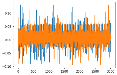
So, it might just have been that the first Husky is broken. During the meeting we tried another one and while the trace visually looks similar, I noticed the numbers were better, and I got to test it now and both the password attack as well as the DPA work with the original numbers, using the new Husky
Maybe the second one is one of the new revisions you mentioned?
Some images with the new Husky:
With the diff, you can even spot 3 spots where all traces except the one for the correct letter are close to 0.